TOP

![]()
![]()
![]()
Norcim Page 36
The Early days of proportional radio control began with analogue control systems. The ‘Staveley’ four channel transmitter, receiver and servos was one of the best available during the late 1960’s. Jean-Marie Piednoir takes a look at the system producing some amazing electronic detail. It is unlikely that such detail still exists from over half a century ago.
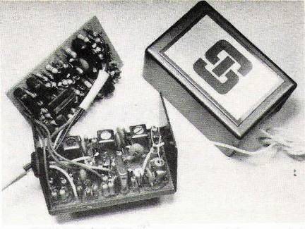
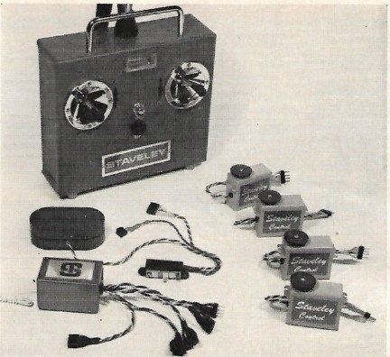 The picture shows the complete Staveley radio control system as it
would be taken out of the box. The dual charger for transmitter and receiver is
built into the lower Tx case alongside the battery.
The picture shows the complete Staveley radio control system as it
would be taken out of the box. The dual charger for transmitter and receiver is
built into the lower Tx case alongside the battery.
The transmitter output is a continuous square wave tone of nominally 500 cycles per second producing a centre position of the aileron channel. Variation of the tone frequency via the aileron joystick moves the aileron servo proportionally one way or the other.
Variation of the mark space of the square wave tone, produces movement of the elevator channel and servo.
With the first two channels working OK, a second very low frequency pulse generator running at 60 cycles per second is superimposed on the tone output of the transmission allowing both the 500 cycles per second to be altered up and down and also the mark space of the tone. This low frequency pulsing offers another two channels for the rudder and throttle servos.
The receiver decoding circuitry employs filters that can distinguish between the true ‘Tone’ frequency and the slower pulsing frequency used for channel 3 and 4, Throttle and Rudder.
So all in all, we have a four channel analogue radio control system.
Staveley, for the day, was extremely well presented. The transmitter case was formed using an expensive looking green vinyl clad aluminium using American ‘Kraft’ joystics and an impressive meter showing true output RF power. The receiver used superhet circuitry, double PCB construction housed in a smart green anodised aluminium case. Servos were top quality of the day Kraft-KPS 10 and or Controlaire S4a mechanics.
Jean-marie Piednoir has produced the following circuitry of the Staveley 4 transmitter loaned by Phil Green of the ‘Single Channel website’ and R/C museum.
The Staveley 4 was one of the milestones in proportional multi channel radio control model history for sure.
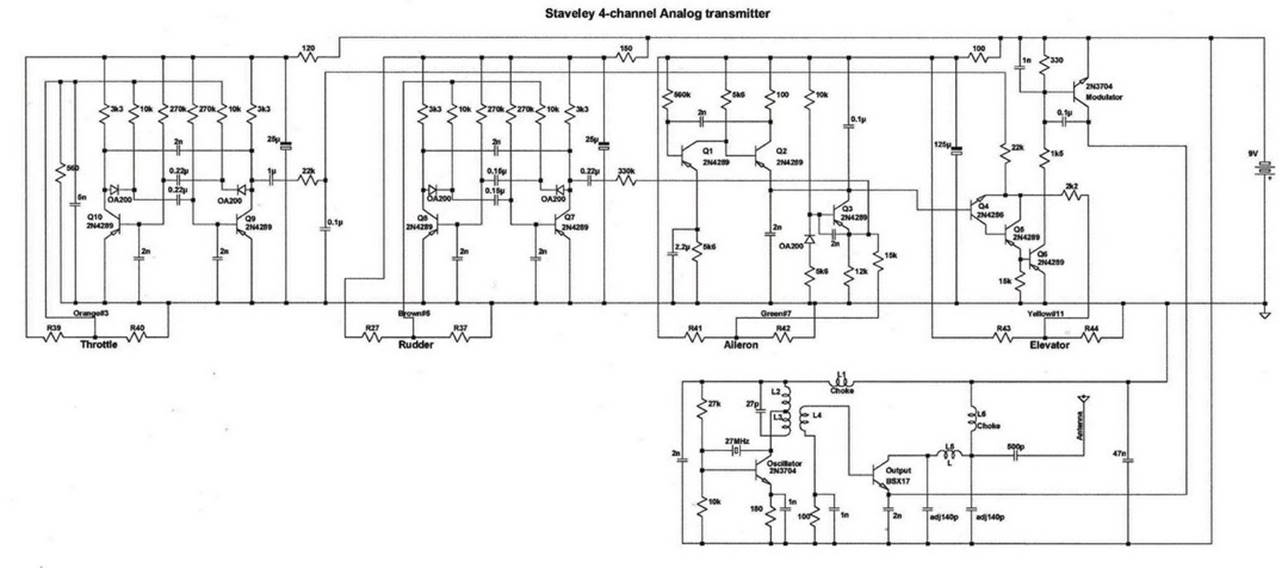
THE STAVELEY 4 ANALOGUE TRANSMITTER
CIRCUIT
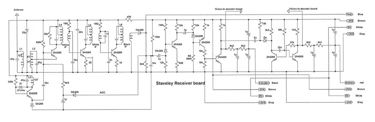
THE STAVELY 4 ANALOGUE RECEIVER
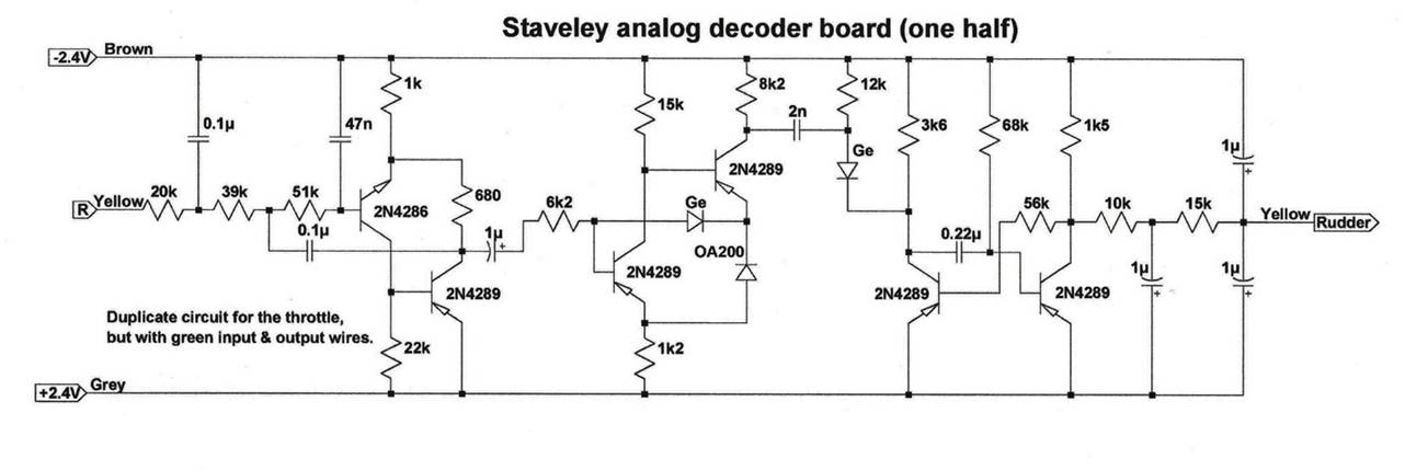
STAVELEY ANALOGUE DECODER FOR
RUDDER/THROTTLE
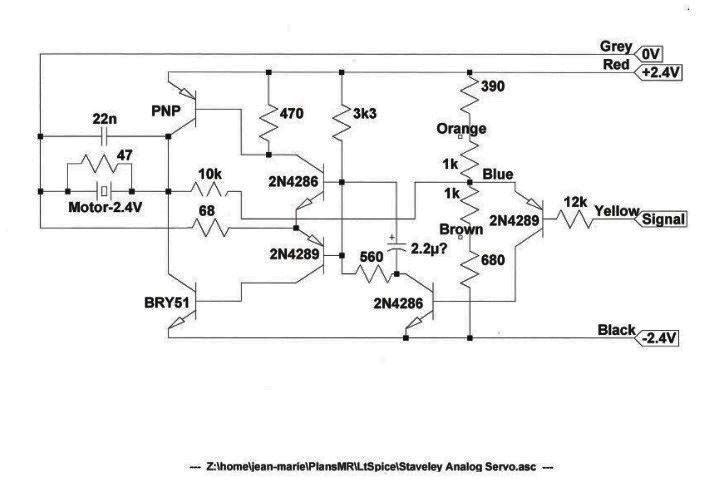
STAVELEY ANALOGUE SERVO AMPLIFIER
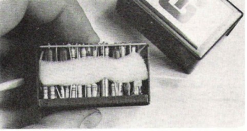
PHOTOS SHOWING
THE STAVELEY ANALOGUE SUPERHET RECEIVER. FOUR FLYLEAD SOCKETS EXTEND FROM ONE
END OF THE CASE FOR SERVOS.
27 MHZ WITH
SOLDER-IN XTAL. SO ONLY ONE INDIVIDUAL CHANNEL FREQUENCY TO ORDER.
Many thanks to Jean-Marie Piednoir for his input. The reading of electronic circuitry
from existing hardware is extremely difficult and very few people have the art
of doing this. Many Thanks J-M.
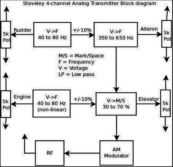 Coder Modulator.
The heart of the
system is the variable frequency oscillator with a frequency centred on 500Hz
variable over the range 350Hz to 650Hz under the control of a voltage defined
by the position the Aileron Stick potentiometer.
The frequency of
this oscillator is also varied by a separate low frequency oscillator centred
on 60Hz and variable over the range 40Hz to 80Hz under control of the Rudder
Stick potentiometer. This approximately +/-10% frequency modulation being
achieved by summing a proportion the low frequency oscillator output to the
main oscillator control voltage defined by the position of the Aileron Stick.
The square wave
output from the 500Hz centred oscillator then subjected to 30 to 70% mark to
space variation under the control of a voltage defined by the position of the
Elevator Stick potentiometer.
The degree of mark
to space variation is similarly varied by a separate low frequency oscillator
centred on 60Hz and variable over the range 40Hz to 80Hz under control of the
Throttle Stick potentiometer in a manner similar to the Rudder control described above.
The complex
modulation waveform following the composite mark to space modulation is then
applied to the RF modulator (another box needed) and thence to the 27MHz rf.
Generator.
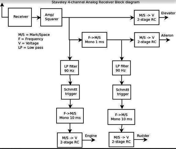
Decoding.
Before describing
the decoder circuit it is necessary to understand that, although frequency
variation or modulation is involved for three of the four functions, frequency
to voltage conversion is not used to provide the dc voltages necessary to drive
the analogue servo amplifiers. The trick is to use detected pulses to trigger monostable circuits with periods equal to approximately
half of the mean periods for the centre frequencies. Thus, the nominally 60Hz
modulated signals trigger 10mS duration monostable
circuits and the nominally 500Hz modulated signal triggers a 1ms duration
monostable. By this method frequency modulation is converted to mark to space
modulation and thence to a mean direct voltage level for application to a servo
amplifier circuit.
The demodulated
signal from the 27MHz receiver is applied initially to an amplifier/squarer
circuit to ensure that all pulses are of full amplitude. Following the squarer
circuit, the signal is directly applied to a low pass active filter circuit
with an abrupt cut off at 90Hz. The filtered output signal is then ‘sharpened’
by a Schmitt trigger circuit to produce full amplitude pulses which in turn
trigger a 10ms period monostable, thereby converting
a variable frequency signal to a variable mark to space signal and thence to a
mean dc level (dependent upon mark to space) to drive the Throttle servo
amplifier.
The output from the
amplifier/squarer circuit is also fed directly a mark to space to voltage conversion
circuit to provide a mean dc level to drive the Elevator servo amplifier.
The unfiltered
output from the amplifier/squarer circuit is also used to trigger a 1ms period monostable thereby converting frequency variations centred
on 500Hz into variable mark to space and hence to a direct voltage to drive the
Aileron servo amplifier. The 1mS monostable output is further applied to a low pass
filter/trigger/ 10ms monostable/ mark to space/ chain
identical to that for the throttle control. By this means a direct voltage to
drive the Rudder servo amplifier is extracted from the low frequency modulation
of the variable frequency oscillation, centred on 500Hz, produced by the
Aileron Stick.
The overall control
system appears to be very ‘Heath Robinson’ in concept but there was probably
little else which could be done in the 1960s. Heaven knows what a six-channel
system would have involved. It is apparent why the so-called digital control
system prevailed.
John-Marie Piedmore’s production of the above schematics must have
involved much effort and in support of with this he employed LT Spice to
display waveforms at various points of the transmitter circuit and to display
the frequency response of the low pass active filters in the receiver circuit.
LT Spice VII is a
powerful ‘free to use’ circuit analysis programme formerly provided by Linear
Technology and currently by Analogue Devices.
The example of its
application shown below is a simulation of a simplified version of the 500Hz master modulation
oscillator, depicting the waveform at the collector of transistor Q3.
Resistors R9 and R10
simulate the Aileron Stick potentiometer at mid position.
As can be seen the output
of the oscillator is a linear saw tooth waveform.
In further
simulations, subject to a total 5k Ohms, values of R9 and R10 may be mutually
varied to demonstrate the frequency range provided by the Aileron stick.
Hello, we are still working on this page
at the moment, Thanks for reading 🛩🛩