Norcim rc
electronics club page 2…..

Possible use of the Micron FET7 receiver on 40 MHz.
This is a ‘Dual Conversion’ receiver and
several enquiries have come in about its possible use on the 40 MHZ band for
model boats and cars. Providing you can get hold  of 40
MHz receiver crystals (preferably Futaba manufacture) then the changes to the
FET 7 receiver are not too drastic! All of the changes are at the front end and
involve the change of the 33uH inductor, (fig 2 on microns drawing) to a 22uH
value available from Farnell Components* part number 513-477. The 27p capacitor
and 4u7 inductor is simply snipped out as not needed on the 40MHz band. The
front 159DZ antenna coil will need re-setting for maximum range using a 40MHz
transmitter and you will find that this will involve almost exactly one turn of
the core further down, clockwise, than the setting for 35MHz. Ideally the 27p
capacitor across the coil would be changed for a 22p but as its under the coil,
this is not practical. If starting from scratch then fit a 22p! The setting of
the ‘L2’ coil (several type numbers were used for this coil) should not need
any alteration.
of 40
MHz receiver crystals (preferably Futaba manufacture) then the changes to the
FET 7 receiver are not too drastic! All of the changes are at the front end and
involve the change of the 33uH inductor, (fig 2 on microns drawing) to a 22uH
value available from Farnell Components* part number 513-477. The 27p capacitor
and 4u7 inductor is simply snipped out as not needed on the 40MHz band. The
front 159DZ antenna coil will need re-setting for maximum range using a 40MHz
transmitter and you will find that this will involve almost exactly one turn of
the core further down, clockwise, than the setting for 35MHz. Ideally the 27p
capacitor across the coil would be changed for a 22p but as its under the coil,
this is not practical. If starting from scratch then fit a 22p! The setting of
the ‘L2’ coil (several type numbers were used for this coil) should not need
any alteration.
If you’r posh! and have an oscilloscope to use when setting up home built receivers, then it is worth realising that the scope lead and scope, when connected to the receiver, adds to the antenna circuit of the receiver! When removed the antenna coil may not be perfectly set! To counteract this effect, a special scope lead can be made using a scope input DIN connector with two half metre, or so, flex wires terminating with mini crock clips or similar, with a 1K resistor in each lead at the crock clip. The resistors filter the RF antenna effect while still allowing the receiver output signal to show on the oscilloscope. The ‘scope output’ on all the Micron receivers is from pin 9 of the 3361 IC after the 4k7 resistor.
If you’r not so posh! and don’t have an oscilloscope, then I have found that reliable tuning of R/C receivers can be done with a ‘crystal earpiece’ costing little more than a Euro (or less than a pound!). They usually come with thin flex wiring, terminating with a jack-plug. If the tip is held on the resistor from pin 9 (micron receivers) with the ‘other metal bit’ resting against the metal can of the coil (or owt that’s negative), then you can plainly hear the transmitter signal as a ‘buzzing’ sound! The discriminator coil, L2 can then be set for maximum ‘loudness’. For setting the antenna coil….put the receiver and battery in a card box and move away from the transmitter until the ‘buzzing’ diminishes slightly. Now adjust the front antenna coil L1 for maximum loudness or reception of the buzzing sound. (note that a ‘hiss’ can be clearly heard either side of the Tx signal buzz). That’s it! And it can be very accurate.
It’s probably worth mentioning that the L2 coil on micron receivers can also be set using a multimeter. With the meter pos’ lead to the pin 9 resistor, and neg’ lead to battery negative, simply adjust L2 to achieve a reading of 2 volts, (with the transmitter switched on!).
>
A Word about Micron transmitters and 40 MHz.
The ‘MICRON 35/40 1996’ transmit sections
always made use of ‘Fleet Control Systems’ crystals for use of the 40 MHZ band.
These were manufactured by the ‘IQD’ crystal company in Somerset and suited the
 Micron
transmitter kit perfectly without any circuit change at all! However these
crystals have been obsolete for some years now. In an attempt to find an
alternative, I have found that the standard Micron transmit section will work
with Futaba 40 MHz crystals providing a capacitor value is changed. The
capacitor in question is the 56p across the base/emitter of the BF450 transistor.
If this is raised to a value of 150p, then Futaba 40 MHz crystals can be used.
The transmit section has to be tuned to the new band using the LED tuning
device that comes with the Micron transmitter kit. A small reduction in range
may result from using these crystals, (as the Tx
crystal is one third of the output frequency unlike the Fleet crystals which
were half frequency) but this can be corrected if necessary by reducing the
100R output transistor, input resistor to 68R. This is probably unnecessary
however, as the range required with model boats, is lower than that required
for model aircraft. Remember, Micron transmitters must use the special
micron loaded antenna and the 40 MHz version must be used
Micron
transmitter kit perfectly without any circuit change at all! However these
crystals have been obsolete for some years now. In an attempt to find an
alternative, I have found that the standard Micron transmit section will work
with Futaba 40 MHz crystals providing a capacitor value is changed. The
capacitor in question is the 56p across the base/emitter of the BF450 transistor.
If this is raised to a value of 150p, then Futaba 40 MHz crystals can be used.
The transmit section has to be tuned to the new band using the LED tuning
device that comes with the Micron transmitter kit. A small reduction in range
may result from using these crystals, (as the Tx
crystal is one third of the output frequency unlike the Fleet crystals which
were half frequency) but this can be corrected if necessary by reducing the
100R output transistor, input resistor to 68R. This is probably unnecessary
however, as the range required with model boats, is lower than that required
for model aircraft. Remember, Micron transmitters must use the special
micron loaded antenna and the 40 MHz version must be used
for this mod. UPDATE 27/8/02 a possible small but significant improvement in output power on 40 MHz can be achieved by reducing the 27p across L1 to 22p. This allows a better position of L1 core, giving a little more RF transfer to the secondary winding.
Another Word about Micron transmitters on the 35 MHz band.
A few constructors of recent Micron transmitter
kits have expressed grave doubts about the ‘range’ or ‘power output’ of their
latest version of Microns offering, as the current consumption of the whole
transmitter is less than 80 milliamps! In my opinion this is totally
understandable as their latest Micron Tx kit consumes
about half the power from the batteries of any other commercial 35 transmitter.
Surely this can only mean half the range!? Micron  however
point out that this is simply not the case and despite the small battery power
needed, the range, even with their mini loaded antenna is still comparable with
the ‘commercial counterpart’ and the answer is simply the use of their loaded
antenna system. To prove the point, R/C Model World magazine March 2000, in their ‘electronics project
series’, covered a ‘Transmitter Output Tester’ that measures the field strength
(power) of any Tx at a distance of 10 metres. I have
used this smart device now many times and conclude, I wouldn’t be without it.
Not only does it show that the Micron Tx output is
comparable with other transmitters but its occasional use with any transmitter
gives great confidence of correct output. All of this becomes more interesting
really, when you consider that the Micron transmitter can work for up to twice
as long as other transmitters, between charges. Good for a day (or two) on the
slope!
however
point out that this is simply not the case and despite the small battery power
needed, the range, even with their mini loaded antenna is still comparable with
the ‘commercial counterpart’ and the answer is simply the use of their loaded
antenna system. To prove the point, R/C Model World magazine March 2000, in their ‘electronics project
series’, covered a ‘Transmitter Output Tester’ that measures the field strength
(power) of any Tx at a distance of 10 metres. I have
used this smart device now many times and conclude, I wouldn’t be without it.
Not only does it show that the Micron Tx output is
comparable with other transmitters but its occasional use with any transmitter
gives great confidence of correct output. All of this becomes more interesting
really, when you consider that the Micron transmitter can work for up to twice
as long as other transmitters, between charges. Good for a day (or two) on the
slope!
Yet another Word! on Micron transmitters
a couple of recent enquiries, ask if the latest
Micron transmit section could be used 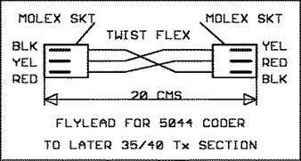 in
earlier Micron transmitters. A quick consultation with Roger Keately at Micron and a search through the mountains of
drawings and sketches he had, suggested that this had been thought about and
indeed possible. The only thing needed is a special connecting flylead to connect the older (excellent but now obsolete!)
NE5044 encoder to the new transmit section. This lead is shown and can be made
up using parts available from most electronic stores or Micron. The odd thing
about this lead is that it can be fitted any way round! ie
there is no specific end which must go to the coder or RF section, the wiring
appears to sort itself out, whichever way round the lead is fitted.
in
earlier Micron transmitters. A quick consultation with Roger Keately at Micron and a search through the mountains of
drawings and sketches he had, suggested that this had been thought about and
indeed possible. The only thing needed is a special connecting flylead to connect the older (excellent but now obsolete!)
NE5044 encoder to the new transmit section. This lead is shown and can be made
up using parts available from most electronic stores or Micron. The odd thing
about this lead is that it can be fitted any way round! ie
there is no specific end which must go to the coder or RF section, the wiring
appears to sort itself out, whichever way round the lead is fitted.
THE FIRST ‘INTEGRATED
CIRCUIT’ SERVOS USED THE WE3141 INTEGRATED CIRCUIT. This
was the first servo IC and was housed in a TO5 metal transistor package and had
ten legs ! It was developed with ‘World Engines’ in 1971 by the Signetics company. The IC worked well but the servo
feedback 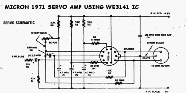 potentiometer was used in ‘variable resistor’
mode. This was it’s downfall ! After a few hours of servo use, the
movement of the servo became extremely twitchy. Also, often when at rest, the
servo would simply sit and ‘jitter’ about its rest position. The only ‘Fix’
recommended by the R/C manufacturers of the time that used this IC, was to
periodically (very!) dismantle and clean the feedback potentiometer of all the
servos used in the system. Most manufacturers who used this IC in their servos
tried many different types of feedback pot and wiper design in an attempt to
alleviate the problem. The problem seemed that the pot surface quite quickly
became contaminated with microscopic bits of the wiper material. This randomly
changed the normal smooth linear effect of the feedback resistance. It
produced an unsure resistor value change with slow movement of the feedback
pot. The servo amp however did exactly what the pot was telling it to do…and
followed faithfully every tiny change of resistance and this was shown
faithfully by the slightly erratic movement of the servo output arm. OK…THE
LESSON had been learned the hard way by the R/C industry.
potentiometer was used in ‘variable resistor’
mode. This was it’s downfall ! After a few hours of servo use, the
movement of the servo became extremely twitchy. Also, often when at rest, the
servo would simply sit and ‘jitter’ about its rest position. The only ‘Fix’
recommended by the R/C manufacturers of the time that used this IC, was to
periodically (very!) dismantle and clean the feedback potentiometer of all the
servos used in the system. Most manufacturers who used this IC in their servos
tried many different types of feedback pot and wiper design in an attempt to
alleviate the problem. The problem seemed that the pot surface quite quickly
became contaminated with microscopic bits of the wiper material. This randomly
changed the normal smooth linear effect of the feedback resistance. It
produced an unsure resistor value change with slow movement of the feedback
pot. The servo amp however did exactly what the pot was telling it to do…and
followed faithfully every tiny change of resistance and this was shown
faithfully by the slightly erratic movement of the servo output arm. OK…THE
LESSON had been learned the hard way by the R/C industry.  All development of later IC’s for servo amps
used the feedback pot as a ‘potential divider’. The small changes of resistance
at the pot surface to the wiper would not be ‘seen’ by the input to the
amplifier. The Signetics NE544 and the Ferranti ZN901
IC servo amps quickly came on the scene. These used the feedback pot as a
voltage divider and the problem was solved. The World Engines WE3141 began the
IC servo amp revolution but owing to the basic design flaw, production was
stopped and availability dried up.
All development of later IC’s for servo amps
used the feedback pot as a ‘potential divider’. The small changes of resistance
at the pot surface to the wiper would not be ‘seen’ by the input to the
amplifier. The Signetics NE544 and the Ferranti ZN901
IC servo amps quickly came on the scene. These used the feedback pot as a
voltage divider and the problem was solved. The World Engines WE3141 began the
IC servo amp revolution but owing to the basic design flaw, production was
stopped and availability dried up.
Having said all of that ! A strange finding by a farmer in Lincoln UK, showed how the WE3141 could be tamed and used successfully ! He was an aerobatic model flier at the time. Being a farmer, he had tubs of Molybdenum Grease for use on the Farm machinery. ( Rocol ASP high % moly grease). Yes….he tried applying a blob of this (costly!) stuff onto the feedback pot and wiper of a Micron/SLM servo of the time. The results were smooth operation of the servo even days later…..and then even weeks later…..and then even months later ! During the early part of this finding, the farmer contacted Micron and ‘Rocol ASP Moly grease’ was added to the pot housings of several hundred servo kits that were sold with the WE3141 IC amp. The cost per servo was just 3p. Customer feedback was fine. Just how this stuff worked, was, and still is a mystery. But it did work ! With the newer servo IC’s coming on the scene, supply of the WE3141 dried up and Micron changed to the NE544.
TRANSMITTER ANTENNAS (telescopic aerials in old money!)
I know you’ve read it before but it is a fact that telescopic aerials were never designed for model use! The caster base fuel gets into these things, dries out into a gum, almost making it impossible to collapse the aerial down without bending or breaking it! If this is not bad enough the ‘grunge’ that’s living in the aerial, sadly reduces the range of the Tx. (simply because of poor electrical contact of each telescopic section). Occasionally, unscrew the antenna, extend it and squirt ‘WD40’ into the bottom screw hole. A few collapses and extensions, using a kitchen towel to clean the antenna will prolong its active life! (Aahhh!). A word of warning though! If the aerial has been left in the ‘grunge’ condition for too long, then after the above servicing, you may find that the top section is so slack that it slides back under its own weight! The only consolation is that the only thing keeping it extended before cleaning, was grunge and this prevented the aerial working correctly anyway. Should this happen, the antenna needs replacing.
An electronic modeller contacted me with an
idea of using a speed controller circuit to keep the glow-plug of a four-stroke
motor, ‘hot’ at low revs and tick-over. Unfortunately the detail of the mail
involved, has disappeared and I now can’t give credit to the guy who was
originally involved. However his idea is shown in the circuit alongside and
involves the modification of 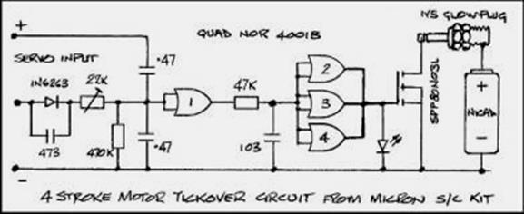 his
Micron speed controller to achieve the above. It is well accepted that 4stroke
motors often ‘cut out’ at low revs or tick-over, particularly when using low nitro
fuels. Some 2strokes can also suffer from this when using less expensive
‘straight’ fuel and could also benefit from this device! The Micron speed
controller is very easy to modify, as it’s a kit! The only mods involved are
the changing of the original 0.22 uF capacitors to a
value of 0.47uF (see circuit) and the addition of a 5v ‘resistorLED’
which shows the glow state of the Glow-plug. The finished unit plugs into the
throttle output of the receiver (together with the throttle servo, so you will
need a two way plug!). The resulting ‘Glow-plug controller’, heats the
glow-plug, (Using an on board nicad battery) from
about quarter throttle, with very little heat, down to full heat at tick-over.
The ‘on board’ nickel cadmium single cell battery needs to be about 2000 mAH or more to last the flying session. Setting up the
controller involves adjusting the 22K trim-pot to just give
maximum brightness to the LED, when the motor is set at ‘tick-over’. You should
then notice that as the throttle is slowly increased, the LED looses intensity
until around a quarter throttle, when the LED (and therefore plug) is not
glowing at all. 2% petrol added to a basic mix of glow fuel often helps with
general performance and tick-over. (more than 2% does not work well) The use of
a ‘synthetic oil’ based fuel compared with castor-based type, ‘in itself’,
helps with both throttling and a reliable tick-over. The petrol mix idea, mixes
with both types of fuel.
his
Micron speed controller to achieve the above. It is well accepted that 4stroke
motors often ‘cut out’ at low revs or tick-over, particularly when using low nitro
fuels. Some 2strokes can also suffer from this when using less expensive
‘straight’ fuel and could also benefit from this device! The Micron speed
controller is very easy to modify, as it’s a kit! The only mods involved are
the changing of the original 0.22 uF capacitors to a
value of 0.47uF (see circuit) and the addition of a 5v ‘resistorLED’
which shows the glow state of the Glow-plug. The finished unit plugs into the
throttle output of the receiver (together with the throttle servo, so you will
need a two way plug!). The resulting ‘Glow-plug controller’, heats the
glow-plug, (Using an on board nicad battery) from
about quarter throttle, with very little heat, down to full heat at tick-over.
The ‘on board’ nickel cadmium single cell battery needs to be about 2000 mAH or more to last the flying session. Setting up the
controller involves adjusting the 22K trim-pot to just give
maximum brightness to the LED, when the motor is set at ‘tick-over’. You should
then notice that as the throttle is slowly increased, the LED looses intensity
until around a quarter throttle, when the LED (and therefore plug) is not
glowing at all. 2% petrol added to a basic mix of glow fuel often helps with
general performance and tick-over. (more than 2% does not work well) The use of
a ‘synthetic oil’ based fuel compared with castor-based type, ‘in itself’,
helps with both throttling and a reliable tick-over. The petrol mix idea, mixes
with both types of fuel.
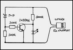 RECEIVER BATTERY MONITOR
this is about the simplest circuit you can get using a simple zener voltage diode (BZX79C3V9 Farnell order code 369-378). The circuit is shown alongside and simply plugs into a spare servo output of the receiver. The idea is that, providing the receiver battery is well charged (4v8 plus), then the transistor TR1 remains conducting at all times and the red LED shows no warning. However as the battery begins to sag, the demands of the servos pull the voltage down below TR1 conduction and the LED flashes. It is important that use of this circuit involves ‘stirring’ two or three servos before and after each flight. If the LED flashes, then it’s time to go home and charge the battery!
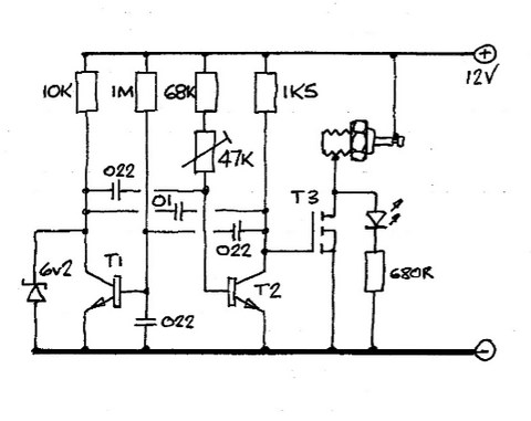
A 12 VOLT GLOW-PLUG DRIVER Please note that this circuit has not been assembled or tested
but it is offered for experiment by those electronic nuts who may wish to assemble it and modify if necessary. Needless to say that if you do dabble and get results (or don’t), then do let the web site know! The circuit is based on a standard text book ‘multivibrator’ and it’s voltage supply is the starter battery used by modellers. It fires a stream of thin 12 volt pulses to the standard 2 volt motor glow-plug, simulating a 2 volt supply. The 47K pot allows adjustment of the width of the pulses to suit the type of glow-plug used (simply adjust the pot to obtain a rich orange glow with the glow-plug used) A zener diode allows automatic fattening of the pulses when the starter motor load abruptly pulls the battery voltage down. T1 and T2 are BC184LC or similar transistors with T3 being a BUZ11A or similar power mosfet. The LED will illuminate when the plug lead is connected to the glow-plug, providing the plug element is intact. The LED should be a high brightness type. T1 and T2 must be high gain type, preferably better than 400 at around 2 mA. Worth a mention is that the glow-plug connector type should be of the ‘box-spanner’ type. The ‘clip on’ type can so easily clip on to the motor body and head causing a short circuit which would not be good news for the BUZ11.
![]()
Thanks for reading.