Norcim rc electronics club page 11……

Previous Page Contents Page
Next
Page
SOME USEFUL LINKS…… ![]() HobbyCity
HobbyCity
![]() GreatHobbies
GreatHobbies
![]() BangGood
BangGood
![]() ModelFlight RC
ModelFlight RC
![]() HorizonHobby
HorizonHobby
‘Notes11’ has had to be started simply cos ‘notes9’ and ‘notes10’ pages are over full again and taking too much time to download for readers. My thanks go to David Caudrey for his ‘reverse engineering’ skills and his original circuit designs. Some of his original designs will be pulled over onto this page. It is good for all of us electronic nuts to see this sharing of R/C technology and history……to use a quote from a link on our home page seems appropriate….’Technology Lives Forever!’
PEAK DETECT CHARGER CIRCUIT FOR NC AND NH BATTERIES MK2 ∆
for nicad and NH type batteries. Many of these batteries are still used by model fliers and model boat people.
David points out that new cells/batteries, should have a first normal timed charge and discharge before using this circuit.
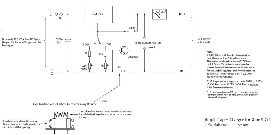
CHARGER CIRCUIT FOR 2 OR 3 CELL LIPO BATTERIES. ∆
This charge circuit fast charges LiPo batteries until near full charge when the charge current very slowly drops to a trickle. The lower current toward the end of charge allows the cells to safely fill and/or balance out. The first schematic on page10 of 'Norcim Notes' is a uA 723 based charging circuit for two or three cell LiPo flight batteries. In the accompanying text is mentioned the possibility of basing a charging circuit on a suitable three-terminal regulator. Attached is the schematic of a charging circuit based on the LM350 regulator. Whilst perhaps not quite as good as the uA 723 version it is much easier to construct using stripboard (standard uA 723 is 10 pin T05 package). I have made several of these to charge all of my batteries simultaneously before going to the flying field. With regard to Lipo charging, the circuit is so simple because I have never found the need for cell balancing. When I first started using early Kokum batteries no provision was made for balancing. I am still using some of them five or six years on.
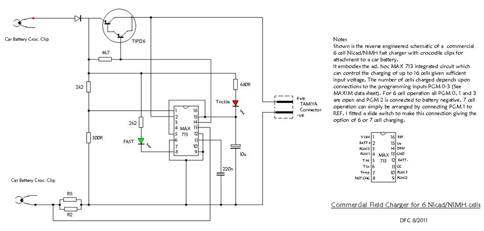
A SIX CELL COMMERCIAL NC/NH FAST CHARGER CIRCUIT ∆
With details of switched modification to charge both six and seven cell battery packs.
ON-BOARD plug-in receiver battery monitor. ∆
David points out that the circuit is sensitive to the forward volt drop of the LEDs
used in this circuit. So select these with a volt drop close to 2.0 volts. (some of the later LEDs use a much higher volt drop and are not suitable).
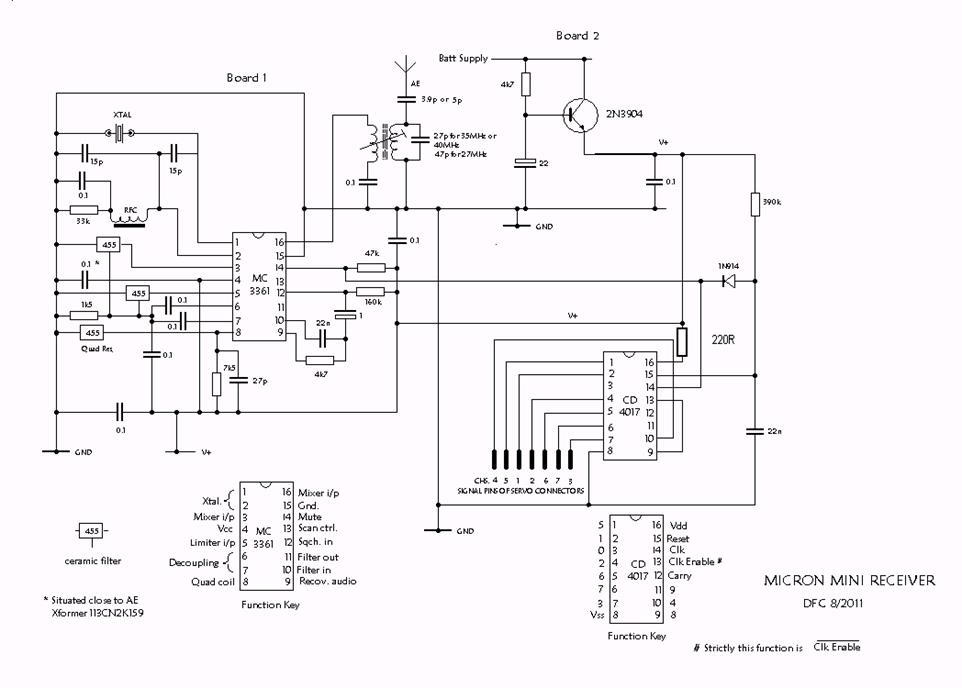
MICRON mini receiver circuit ∆
These historic R/C receivers were one of the smallest units of their time. They were available in electronic kit form and ready assembled.
The circuit was suitable for the 27, 35 and 40MHz bands with minimal component change. Thousands sold to many parts of the world.
Noted for there excellent range, these receivers also worked with almost any transmitters available. Later versions used a combination of mechanical and ceramic filters which gave good 10KHz frequency spacing. Motorola eventually ceased manufacture of the 3361 narrow band frequency modulated IC and sales of the micron receiver diminished. It is interesting however that over fifty thousand of MC3361CD are still available on obsolete electronic component sites.
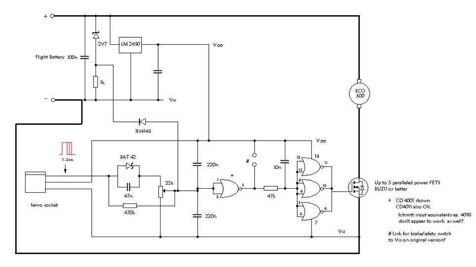
MICRON speed controller circuit. ∆
Simple speed control circuit using CD4001 IC. Requires full line voltage swing input from receiver for best results. Can be used without the LM2490 for simplicity but slight speed variation occurs with control servo movement. Two mini servos OK.10 to 40 amps with good FETs. Must be logic level input FETs.
SERVO AND SPEED CONTROLLER TESTER ∆
This circuit was developed to work with almost all available manufacturers R/C servos and speed controllers.
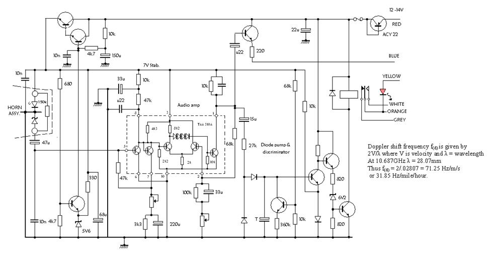
A REVERSE ENGINEERED CIRCUIT OF A MOVEMENT DETECTOR ∆
David has in mind the possible development of this circuit to work as a Speed Gun for use with model aircraft, boats and cars.
A REVERSE ENGINEERED NICAD RECYCLING CIRCUIT ∆
Attached is a part schematic of a nicad 'cycler' which was available in the 1990s. Mine was initially unreliable due to the coarseness of the setting of the 10k potentiometer used to determine the end point voltage. Replacing this with a lower value potentiometer, used in conjunction with two fixed resistors, greatly improved the reliability.
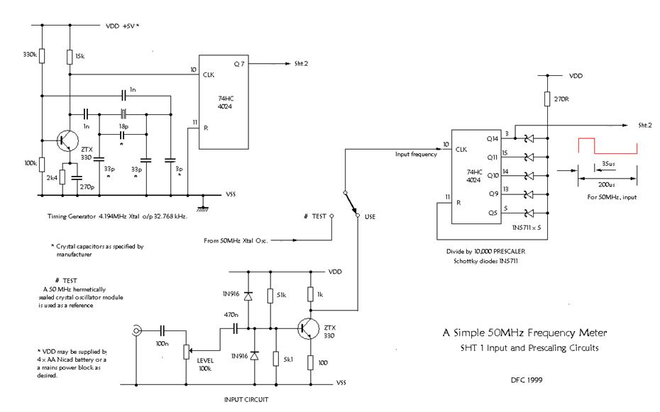
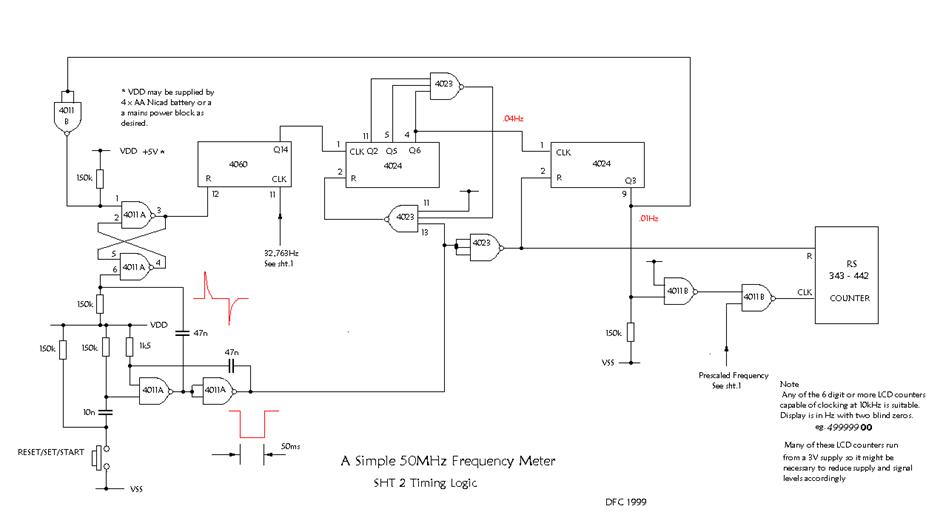
THE
ABOVE TWO CIRCUITS cover an original design of a Frequency Meter. The circuit is
capable of  displaying the frequency
of model control transmitters using the 27MHz, 35MHz and 40MHz bands. Both AM
and FM modulation transmitters can be used. Note that with the typical PPM type
modulation used with these transmitters, the display will often show around one
KHz low of the actual crystal frequency. (as with all
frequency counters). This is due to the Tx
coder spending most of its time in a LOW state except for pulses which are
HIGH. This happens with both AM and FM systems. David C points out that with AM
transmitters, correct frequency will be displayed if the coder is disabled
during the test. With FM transmitters, there is an advantage in being able to
stop the coder in both the LOW and HIGH state to display the frequency
deviation. Normal deviation would be plus and minus 1.5KHz
of the crystal frequency.
displaying the frequency
of model control transmitters using the 27MHz, 35MHz and 40MHz bands. Both AM
and FM modulation transmitters can be used. Note that with the typical PPM type
modulation used with these transmitters, the display will often show around one
KHz low of the actual crystal frequency. (as with all
frequency counters). This is due to the Tx
coder spending most of its time in a LOW state except for pulses which are
HIGH. This happens with both AM and FM systems. David C points out that with AM
transmitters, correct frequency will be displayed if the coder is disabled
during the test. With FM transmitters, there is an advantage in being able to
stop the coder in both the LOW and HIGH state to display the frequency
deviation. Normal deviation would be plus and minus 1.5KHz
of the crystal frequency.
All page technical content supplied by David Caudrey April 2011

THANKS FOR READING….. norcimguy at gmail dot com