Spread-Spectrum RC
Systems, How they started and how we got there.
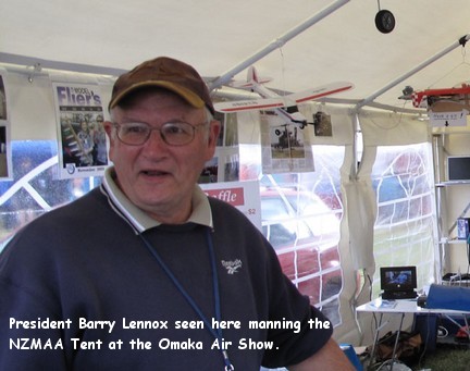
By Barry Lennox
NZ.
PREVIOUS PAGE CONTENTS PAGE NEXT PAGE
A
few weeks ago, Barrie Russell (of the MFHB club NZ) leaned on me looking for an article This is a
bit of a struggle, as I feel like I have written on just about everything that
modelers could possibly be interested in, but there’s still one or two yet,
(But not too many more).
 Several years ago, I did suggest that one day we would all be flying
with Spread Spectrum (SS) radios, but it’s hard to see the future, otherwise
I’d be very, very, very rich indeed !
However, one thing that has fascinated me for years is SS communications,
and have been working with them since the mid 90’s.
Several years ago, I did suggest that one day we would all be flying
with Spread Spectrum (SS) radios, but it’s hard to see the future, otherwise
I’d be very, very, very rich indeed !
However, one thing that has fascinated me for years is SS communications,
and have been working with them since the mid 90’s.
Firstly,
there’s two main varieties that you will come across. The first is a frequency
hopper (FH) It’s pretty self-explanatory, instead of just sitting on one
channel, say 35.02, it just hops about over maybe 20-50 channels at many times
per second. So if one or two or even several channels are busy, or jammed, the
data will still get through, albeit at a reduced rate sometimes. (Futaba uses
this version)
Here’s
a screen shot from a spectrum analyser covering the
2.4 GHz band from 2.4 to 2.485 GHz with a FrSKy FH
transmitter in action. You can see about
50+ channels that are being hopped over. Note that this was averaged over 15
seconds, so there are many “hits” on each channel.
The second type is Direct Sequence Spread Spectrum
(DSSS) Here the 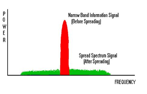 narrow band signal is mixed with a pseudo-random one that is much wider,
or broadband. The resulting signal takes on the characteristics of the wider
signal, so narrow-band noise or interference gets suppressed by the width of
the new signal. If this seems a little hard to understand, don’t worry about
it, just regard it as trickery by maths, however, it
does work very well. (Spectrum and the
first JR sets use this)
narrow band signal is mixed with a pseudo-random one that is much wider,
or broadband. The resulting signal takes on the characteristics of the wider
signal, so narrow-band noise or interference gets suppressed by the width of
the new signal. If this seems a little hard to understand, don’t worry about
it, just regard it as trickery by maths, however, it
does work very well. (Spectrum and the
first JR sets use this)
Here’s a sketch of how the DSSS works. (See Right) >>>>>>>>>
Notice how the signal is dramatically spread, in fact
it generally looks like noise. But it can be reconstructed into the original
narrow-band signal, IF the code is known.
(and that’s a BIG IF, as we will see later). Remember the spreading (and
de-spreading code) is pseudo-random. If it was truly random, there would be no
way of ever recovering the original signal.
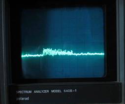
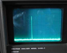
Here’s a spectrum analyzer display of a DSSS
transmitter, note how it’s not much above the noise level. And that’s followed
by another display, nothing has changed, except that the DSSS mode is now
turned off. So it’s now a narrow-band signal, just like say, on 35.05 MHz.
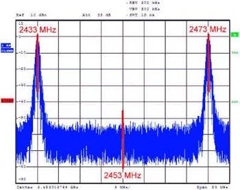
Next,
shown below, is a spectrum analyzer plot of a Spektrum
DX-6. It can be seen, there are two signals, one at 2433 MHz, and the other at
2473 MHz, that are separated by 40 MHz. The signals are sent alternately.
Zooming in on the 2433 MHz signal reveal that it has about a 830 kHz bandwidth.
Remember that our normal narrow-band radios have a bandwidth on only about 12 Khz, so the Spektrum signal has
been spread by a factor of about 70 times, plus, the signal is alternately
transmitted on two quite separate channels for redundancy.
 “Which is best” is the question all poised on your lips. More on that
later, and the real answer is “It all depends” However, the above plot of the Spektrum does give us a clue: That the best system will combine elements of
both FH and DSSS.
“Which is best” is the question all poised on your lips. More on that
later, and the real answer is “It all depends” However, the above plot of the Spektrum does give us a clue: That the best system will combine elements of
both FH and DSSS.
So,
where did all this trickery start? The answer is much further back than you
might think, certainly long before any of us existed. The very first suggestion
was from Nikola Tesla, who filed a patent in July 1900 (the 1903
Tesla
came up with the idea after demonstrating the world's first radio-controlled
submersible boat in 1898, when it became apparent the wireless signals
controlling the boat needed to be secure from "being disturbed,
intercepted, or interfered with in any way." His patents covered two
fundamentally different techniques for achieving immunity to interference, both
of which functioned by altering the carrier frequency. The first had a
transmitter that worked simultaneously at two or more separate frequencies and
a receiver in which each of the individual transmitted frequencies had to be
tuned in, in order for the control circuitry to respond. The second technique
used a variable-frequency transmitter controlled by an encoding wheel that
altered the transmitted frequency in a predetermined manner.
So
far, so good, Piece’o’ cake really. However, the huge (insurmountable actually
then) problem was to ensure that the transmitter and receiver stayed in
synchronization with each other. He
never solved that bogey.
The
next mention of frequency hopping is in a very old text by the radio pioneer
Jonathan Zenneck's book Wireless Telegraphy (German,
1908, English translation McGraw Hill, 1915), and Zenneck
claims that Telefunken had already tried it several years earlier. Zenneck's book was a leading text of the time, and was
highly regarded as the “Wireless Bible”
It is now believed that the German military made limited use of
frequency hopping for communication between a few fixed command points in World
War I to prevent eavesdropping by British forces, who did not have the
technology to follow the sequence, or were even aware of it. However, no
equipment, documentation or reliable memories can be found these days.
Then
in 1929, a Leonard Danilewicz who was working for the
Polish General Staff's Cipher Bureau, proposed a system for secret wireless
telegraphy that : “was a truly barbaric idea consisting in constant changes of
transmitter frequency” Incidentally,
he was also involved in developing parts of the infamous Enigma cipher machine,
widely used by all German forces in WW2.
The
most celebrated version of frequency hopping was that of the very attractive
actress Hedy Lamarr and composer/friend George
Antheil, who were experimenting with “alternative” music and the electrical
control of musical instruments. In 1942 this pair received U.S. Patent
2,292,387 for their "Secret Communications System". Lamarr had learned at defense meetings she had attended
with her former husband Friedrich Mandl that
radio-guided missiles' signals could easily be jammed. So, Hedy and George
concocted a version of frequency hopping that used a piano-roll to hop among 88
frequencies, and was intended to make radio-guided torpedoes harder for enemies
to detect or to jam.
As
far as is known, they never solved the huge problem of synchronization, to
produce a fielded system. Not surprising really, can you imagine trying to get
one piano-roll working correctly, let alone two of them in synchronization!
It
has become a popular myth that they invented SS comms,
that is not true, what they patented was the use of the piano roll. But the
media and the Internet never lets facts get in the way of a “human interest”
spin !
 Incidentally, many years later in the 1970’s Hedy Lamar got a not very
complimentary lampooning in that zany spoof movie “Blazing Saddles” She really
took exception to this, and she and the producer settled out of court for some
undisclosed sum.
Incidentally, many years later in the 1970’s Hedy Lamar got a not very
complimentary lampooning in that zany spoof movie “Blazing Saddles” She really
took exception to this, and she and the producer settled out of court for some
undisclosed sum.
For
several years during the 1990s, the boxes of CorelDRAW's
software suites were graced by a large Corel-drawn image of Hedy Lamarr, in tribute to her pre-computer scientific
discoveries. These pictures were winners in CorelDRAW's
yearly software suite cover design contests. Far from being flattered, however,
Lamarr, once again, sued Corel for using the image
without her permission. Corel countered that she did not own rights to the
image. They reached an another undisclosed , but rumored to be $250,000,
settlement in 1999. Here’s that picture;
The first really successful SS system
was used during WW2 and was developed over a couple of years by about 600
engineers, technicians and mathematicians at Bell Labs. This was known as
SIGSALY or “Project X”
SIGSALY was a secure voice system
that was used to communicate between major command and HQ centers from 1943
onwards. There were only 12 terminals ever made, and no wonder, A SIGSALY
terminal was massive. Consisting of 40 racks of equipment, it weighed over 50
tons, and used about 30 kW of power, necessitating an air-conditioned room to
hold it. The system was cumbersome, but
it worked very effectively. When the Allies invaded
Bell Labs had solved the
synchronization problem by recording random noise on a phonograph record (younger readers, ask your dad what these
are!) The records were played on turntables, but since the timing – the clock
synchronization – between the two terminals had to be precise, the turntables
were by no means just ordinary record-players. They were precision devices, and
the rotation rate of the turntables was carefully controlled, but the system
owed as much to extremely complex mathematics as superb engineering. The records only held 20 minutes of random
noise, but this was mathematically expanded to cover a whole Crypto-period,
being one day.
This was the first working SS
system. Incidentally, the principles involved were still classified until the
1970’s.
Then, one of the lessons learnt by
the Western forces during the Vietnam conflict was that just about any kid with
a cheap scanner and a few add-ons could intercept, direction-find, jam and
generally mess-up your communications quite badly.
The response to this was to turn to
once again, SS systems. The ground forces use the 30-88 MHz band with FM, and
the system developed was known as SINCGARS, and frequency hops 111 times a
second. Nearly every western military
service uses this nowadays with around 600,000 sets being manufactured. Air
forces use a different band, modulation and system. It’s AM in the 225 to 400
MHz band and the system they developed is HAVE QUICK. Again, just about every
western air force now uses HAVE QUICK routinely. These systems offer a
reasonable degree of protection against unsophisticated interception and
jamming techniques. Initially, they were regarded as being a secure system, or
close to it, but of course, within about 2 years a number of manufacturers
(including Rohde & Schwarz, Marconi, Racal, Harris, Thomson-CSF and Tadiran) all offered systems that could once again could
intercept, direction-find, jam and generally mess-up your fancy new SS radios.
You may have noticed that all these
system use frequency hopping. The other commonly used technique (DSSS) is also
widely used these days in many communications systems, but probably the one you
will all be most familiar with is GPS.
The GPS signal from the satellites is actually very narrow band, about
70 Hz wide, but it spread out over 1 MHz for transmission. I.e. about 14,300
times ! And that’s just for the
commercial CA code, the “P-Code” which is only available to restricted users is
spread out to about 10 MHz, ie, 10 times the CA code.
There’s many more, ie;
Bluetooth, which is a frequency hopper, hopping between channels at 1600 times
per second. And then there’s 3G cellphones, Wireless LANs, and all manner of
medical, security and industrial application, even cheap garage door openers,
remote meter readers, remote tyre pressure monitoring
on some high-end cars, and baby
monitors.
So how does all this fit into model
control? Well, several years ago, a
clever company in the USA, Cypress Semiconductors, introduced a cute little
chip, a complete 2.4 GHz SS radio on a chip, the Cypress CYWUSB6935 Transceivers
The datasheet described it as a programmable Radio System-on-Chip (PRoC™) device and is the world’s first low cost flash
programmable microcontroller with an integrated 2.4-GHz radio transceiver.
Their list of suggested uses included about 20 market sectors, including “toys”
It’s interesting to note that in the early days,
Anyway, an equally clever engineer,
Paul Beard, noticed that this device might make a very good RC system. It’s
power output was a little low at just 1 milliWatt,
but an external amplifier-on-a-chip, the SE2526A, soon fixed that. Hence the
original DX-6 was born, (although originally for RC car control) it also used
some older JR mechanics, and cases.
Needless to say, technology does not
stand still, and now both FH and DSSS systems are readily available form many
vendors. This has come about by the relentless march of technology, smarter
engineering, reverse engineering, and dare I say it; Chinese copies!
Incidentally the original CYWUSB6935 is now obsolete
So, where are we at now? The various systems are spreading rapidly,
with every major manufacturer, and many smaller ones all offering SS systems.
The major advantage is that they
allow interoperation without worrying about pegboards and the idiot that might
shoot you down.
They also do not suffer from
electrical interference we tend to get with poorly installed electric motors.
Please do note that they are NOT immune to interference as is often claimed.
And in fact, they are dead easy to interfere with. However, the good news is
that interference off motors, ESCs, etc, runs “out of
puff” at a little over 1 GHz, so by operating at 2.4 GHz, the problem is neatly
bypassed.
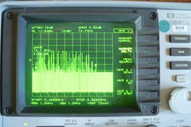
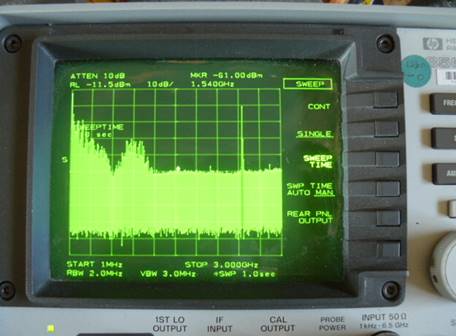
To make this clearer, here is a
screen-shot of a spectrum analyzer looking at an old, unsuppressed and noisy
electric motor. The white marker dot in the
centre is sitting at 1.5GHz, and the “spike” on the right is a FrSky transmitter. Notice there’s no significant energy
past about 1.2 GHz. Also, note that each
graticle line is 10dB (or 10x) so the motor noise
down at around 20-50 MHz is about 1000 x greater than the background noise at
2.45GHz.
 So, now you can see why 2.4GHz systems apparently
“handle interference very well” They
don’t really, but quite simply, the interference is not there !
So, now you can see why 2.4GHz systems apparently
“handle interference very well” They
don’t really, but quite simply, the interference is not there !
And of course, they are very cheap
indeed.
On the other side, there’s several
systems, and none of them are compatible, so you have to make a bit of choice
and stick with it. But, they are very
cheap if you want to change horses. You
should also be aware that they are not quite as immune to interference as the
marketers and advertisers would have you believe. A strong signal will knock
them out very easily. But it’s also true that MOST users of the 2.4GHz band are
restricted to low power. Some are not however, and you must understand and
accept that this band is a bit of a “Wild West” where pretty much anything
goes, and what’s more, you must accept interference whenever and wherever it
happens, it’s clearly part of the terms of the Licence
granted to these devices.
There was reportedly some significant
problems with some of the early systems, such as being shipped with the same
binding code, and the sensitivity of some sets to low battery voltage, but most
of these matters have now been discovered and remedied.
Now, back to the question, which one (FH or DSSS) is
better. Well, there’s no simple answer to that, it all depends on the RF
environment you are operating in, and what the threats are. A simplistic view
is that DSSS ensures data robustness, and FHSS allows the wireless signal to
"hop" to new channels once interference becomes too great.
It is interesting to note the
following comment from Spektrum:-- “Originally,
Spektrum engineers started their development with
FHSS-based systems because they were relatively easy and inexpensive to develop.
However, it was soon discovered that FHSS had several limitations that would
prevent it from being the optimal solution for RC. While more difficult and costly to develop,
our engineers began experimenting with Direct Sequencing Spread Spectrum and optimized
the modulation scheme to overcome critical response and re-link issues. In
addition, DSSS offered 18dB increase of processing gain for significant
improvements in range. With years of development and testing the DSSS
modulation scheme was optimized for RC car use and Spektrum’s
DSM system was born.” (So, now the
wheel has turned full circle and Spektrum has also
moved to FH systems.)
OK, so which is better? Part of the answer is given by various texts,
including the daddy of them all. “Spread Spectrum” by RC Dixon, but be warned,
the maths is heavy going!
There was an excellent article in
“RF Design” a few years ago, comparing FH and DSSS systems in the face of
severe interference. The slight edge was held by DSSS systems, all other things
being equal, but in our environment with moving transmitters and receivers and
all the other variables, things are far from equal. And most systems now combine some elements of
both FH and DSSS systems. Ie, they might be a DSSS
system, but retain the ability to hop around a bit if the RF environment gets a
bit busy.
So, the answer today, will be: what
works best for you !!
Nowadays, most SS RC systems operate
in the 2.400 to 2.483.5 GHz band. The precise terms vary a bit around the
world, some countries permit 100mW, some less, usually 10 mW
and some more. Here in NZ, we operate under a no-charge GURL (General User
Radio License) and it’s a bit of a free-for-all with many thousands of users
with WiFi, cordless phones, alarms, data-links,
microwave ovens, Ham radio transmitters and many other devices. However, there are conditions, and these
include:
·
All equipment must be type-approved.
·
Power must not exceed 4 Watts EIRP (That includes the
antenna gain)
·
If you interfere with a radio or spectrum license
holder, you must stop.
·
RSM does not investigate interference to General User Licences because frequency use is on a shared basis and the
chief executive does not accept liability under any circumstances for any loss
or damage of any kind occasioned by the unavailability of frequencies or
interference to reception.
There, I didn’t
answer the question, but hope that you have found this article interesting.
Some
of our readers may be aware that Barry is the current President of ‘Model
Flying
A baby boomer now, semi-retired,
semi-consulting, and living on a few acres in Nth Canterbury with wife of 41
years, plus a dog, 3 chooks, 3 alpacas,
2 cats and a pond-full of goldfish.
I have spent nearly all my working
life in the electronics industry, much of it in the RNZAF as an Avionics
Engineering Officer, but also several years in commercial aerospace,
secure/special communications, the IT industry and a UAV start-up.
Qualifications are many and varied civil and military ones. I still am a
practicing engineer in things like RF engineering, EMC, electromagnetics,
antennas, etc.
I have been modeling for many years,
on and off. And have dabbled in most areas, free-flight, control line,
rubber-powered, gliders,sport and scale. This all
started when a 3rd form Ham friend suggested a joint project, I build the model
and he built the RC gear. The transmitter was a very wobbly, non-xtal controlled, approx on 27MHz
with a couple of 3D6 valves liberated from Army stores by a friendly Cadets
Army Seargent.
While the receiver used a hearing-aid valve, and a couple of these
new-fangled transistors, imported from Henry's Radio in
Barry Lennox 2013
Many Thanks to the
Hawkes Bay Flying Club for co-operation with this article. …….

There
is relating input about 2.4 Gigahertz
Radio Control on Page18 of Norcim