Norcim rc electronics club page 9……

![]()
![]()
![]()
PLEASE NOTE THAT THIS PAGE IS NOW IN TWO PARTS…FOR PART TWO CLICK HERE
SOME USEFUL
LINKS……. ![]() HobbyKing
HobbyKing ![]() RS
RS ![]() RFcandy
RFcandy ![]() HobbyStores
HobbyStores ![]() Farnell
Farnell
This page is devoted to the ‘reverse engineering’ and original designs of David Caudrey. David’s day job involves some of that very micro tiny stuff called ‘Nuclear Physics’ but more importantly to us! He has been a model airplane nut over the most important years of the UK development of world leading Model Radio Control Systems. These early boom years of the UK late sixties/seventies to the early eighties, produced a powerhouse of model R/C electronic design. Many entrepreneurial skilled people left their ‘day jobs’ to set up very profitable R/C businesses. The following is a list of UK radio control manufacturers during the boom years of the seventies. The list does not include imported R/C products :-
SKYLEADER RADIO CONTROL, FLEET R/C SYSTEMS, SWAN RADIO CONTROL, GEM RADIO CONTROL, HORIZON RADIO CONTROL, FLIGHT LINK SYSTEMS, SPRENGBROOK RADIO CONTROL, MICRON RADIO CONTROL, CENTURY SYSTEMS R/C, REFTECH UHF RADIO CONTROL, WALTRON R/C SYSTEMS, WORLD ENGINES, RCS RADIO CONTROL SYSTEMS, REMCON R/C, MICROCONTROL R/C, PECON RADIO CONTROL, STAVELY CONTROL SYSTEMS. (please note that ‘Micron Radio Control’ are still in involved some 30 years after the demise of the UK R/C manufacturing businesses!)
Sadly, and similar to our wonderful Full size World dominating Aircraft designs and motorcycle industry, this period of almost UK domination of specialist manufacturing and production slowly came to an end. At least the rest of the commercially developing world must have looked on at these British inventions and undoubtedly began their development of bigger and better R/C systems.
OK..nuff of that!! Let’s get back to David Caudrey and his ‘reverse engineering’. This is the stuff that leading car manufacturers do! They acquire vehicles from other manufactures and painstakingly, completely, and with great care, take them apart! This procedure slowly leads right back to the original design stage of the vehicle and every single part! They end up with accurate design drawings of each part, and a load of bits! This information however greatly influences their next ‘Original Design!’ There is nothing wrong with this practice! it goes on for all products and in the end, produces better overall things for us to buy!
The following circuits are by David Caudrey. Some are ‘reverse engineered’. Some are original designs. All are real interesting to electronic R/C nuts like ourselves. Sincere thanks to David for adding these to the norcim website.
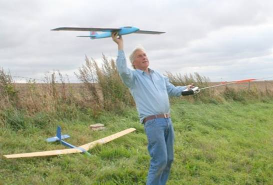
David Caudrey showing his main model interest ‘sloping’ on what looks like a superb day. Recon the landing is done just behind those bushes. Sadly editor Dave Hughes of ‘Radio Modeller’, his flying buddy, was not able to be with him at this time. The transmitter I am sure is a ‘Fleet Radio Control’. Just one of which he ‘reversed engineered!’ The flying site is ‘Watership Down’ (remember the rabbits?).
The picture below is of a refurbished Simplex (an American gas model circa 1941). Has a 600 size motor with 3:1 reduction gears powered by a 3 Cell Lipo Battery. Designed for a Brown Junior with all of the necessary ignition gear, it has come out tail heavy. However, with such a long moment arm it should be flyable without adding lead to the nose which I am reluctant to do. I originally flew it free-flight with an ED 3.46 and two clockwork timers up front. With this arrangement it balanced at 30% chord. The electric drive weighs about the same but the control loops etc. have added a little weight aft. Because of the very short nose a little extra weight aft needs a lot of weight forward to compensate.
I might fit it with one of the little video cameras in the nose as this could be considered to be 'useful weight'. The first picture (left to right) shows the refurbished Simplex model ‘electrified’. The second picture is of a typical Brown Junior petroil motor of the time. The last picture is taken from a 1939ish magazine advert. The full size advert shows Very impressive graphics considering the advert is now 72 years old!
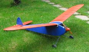
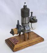
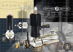
VINTAGE SIMPLEX MODEL TYPICAL BROWN JUNIOR BROWN JUNIOR 1939 ADVERT
SKYLEADER transmit section FM 35 MHz ∆
Starting from the left, the first two transistors simply slow both edges of the incoming coder square wave pulses. This directly controls
the bandwidth of the transmitter, producing narrow band performance. The Xtal oscillator (next transistor) runs with a 17.5 MHz fundamental
crystal. (fundamental crystals can be ‘pulled’ off frequency) +/- 0.75 KHz. Frequency doubling takes place to 35 MHz band. The P.A. stage feeds
the telescopic aerial through coil filters to reduce harmonic content.
All the transmit circuits shown here are F.M. type (frequency modulated).
SKYLEADER 7 channel coder board using NE5044 Signetics IC ∆
Now difficult to get hold of the NE5044 as production ceased many years ago. There may still be small quantities
available via surplus electronic component people.
SKYLEADER TRANSMITTER BATTERY ARRANGEMENT 2 X 4V8 NICAD PACKS ∆
SKYLEADER MAINS CHARGER CIRCUIT. 2 x OUTPUTS FOR BOTH 4V8 TRANSMITTER PACKS AND A 4V8 OUTPUT FOR
THE RECEIVER BATTERY. FULL CHARGE AROUND 14 HOURS ∆
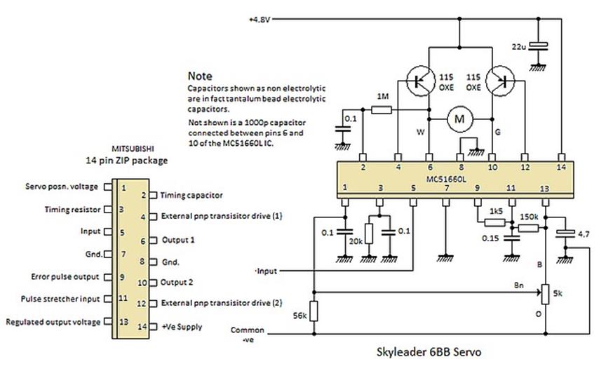
SKYLEADER SERVO AMPLIFIER USING THE MC51660L SERVO AMP CHIP. (A MITSUBUSHI VERSION
OF THE MOTOROLA MC544) ∆
JR 35Megahertz transmit section ∆
Very similar to the above circuit so use the basic description above. The double tuned top coupled coils driving the P.A. stage
is interesting.
MICRON 35 MHz competition receiver and decoder ∆
The description of this receiver is covered on page 1 (this is a better schematic!)
A typical installation of this receiver in DC’s model glider is shown on Page18.
PLEASE NOTE THAT THIS PAGE IS NOW IN TWO PARTS…FOR PART TWO CLICK HERE
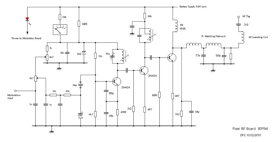
FLEET 35MHz transmit section ∆
Again similar circuit to the top Skyleader circuit so use that description. A neat uncluttered circuit simplified but
meets the required regulations for 35 and 40MHz
FLEET XP FM basic encoder circuit ∆
Typical of the period NE5044 (Signetics) circuit. This I.C. provided R/C manufactures with a superb alternative to the original transistor
‘half-shot’ type circuit designed by Doug Spreng and Don Mathers for early space satellite communication.
FLEET XP FM ENCODER joystick and Aux control amplifiers ∆
NOTE….David Caudrey has a R/C relavent tutorial of Op-amps and their applications on page 13 of this site.
FLEET XP FM ENCODER ancillary controls ∆
The Fleet encoder makes use of operational amplifiers to provide an analogue mixing capability similar to that provided by
modern micro processor based transmitters.
Of particular interest is the method of effecting servo reversal; using potentiometers in lieu of the more usual reversing switches or reversible plug and
socket connections. As an added bonus these potentiometers may be used to determine servo throws – a sort of rates on every channel facility.
Also apparent is the use of separate potentiometers for trims which must have made XP-FM transmitters costly to manufacture; not only for the cost of the additional components but more so for the cost of additional wiring and special stick assemblies.
From a servicing stand point, the XP-FM encoder circuit board is not easy to work on; being very crowded with a multiplicity of wires soldered directly to
the tracks. For those wishing to use the schematic for servicing, LM324A is the separate IC on the right hand side of the board, LM324B is the
central one and LM324C is on the left viewing the board in its normal position in the transmitter. DFC 2011
FUTABA ATTACK AM TRANSMITTER circuit ∆
A 2SC1675 is used as the third overtone oscillator, driving the 2SC2314 PA stage. Both stages are blipped OFF with the control
Pulses from the 2SA833. A single pi-network filter is used to couple the short telescopic aerial. A 2.2 mH choke
is used to resonate the aerial at the output frequency. (27MHz)
FERRANTI ZN409 SERVO I.C. used as an electric flight motor switch by FLEET CONTROL SYSTEMS in the seventies. ∆
PLEASE NOTE THAT THIS PAGE IS NOW IN TWO PARTS…FOR PART TWO CLICK HERE
thanks for reading!
All page technical content supplied by David Caudrey Jan 2012