
PAGE 26
![]()
![]()
![]()
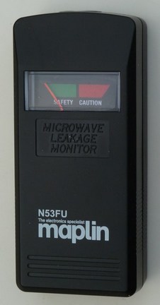
USING MAPLIN’S ‘MICROWAVE LEAK DETECTOR’ FOR A QUICK 2.4 GIG TRANSMITTER OUTPUT CHECKER.
It’s pocketable! Batteries not required! Should last for years! Costs just £4.99. Very difficult to explain why you don’t have one if you use the 2.4 Gig model band!
This pocket size meter that needs no batteries is ideal for a quick check of your transmitter at home or at the field. It works well with all 2.4 Gigahertz transmitters that have a short vertical aerial. It gives a full scale deflection holding the meter next to the aerial (touching). For transmitter testing the red and green bands on the meter mean nothing. The important thing is how far the needle goes over to the right hand side.
The picture below shows the detector alongside a transmitter on a non-metallic surface. (wood, plastic etc). In this position the half scale needle position is normal for most long range transmitters. Short range transmitters used for model toy cars and toy drones may show less deflection of the needle.
Note that the unit is not particularly suitable for transmitters that use an ‘inside aerial’ i.e. a transmitter which has no short 6 to 9 inch of plastic/rubber aerial extending from the top of the transmitter case. These ‘inside aerial’ transmitters use two aerials inside the case at different angles, usually part of the copper print on the printed circuit board. The detector finds difficulty showing a realistic output with these transmitters.
Dimensions =100x45x22
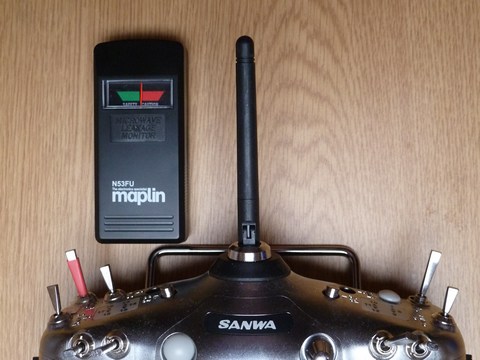 This picture (left) shows the Maplin Microwave
Detector positioned alongside a typical 2.4 Gigahertz high range transmitter
aerial. The detector shows a typical half scale reading. The table top was wood
(not metallic).
This picture (left) shows the Maplin Microwave
Detector positioned alongside a typical 2.4 Gigahertz high range transmitter
aerial. The detector shows a typical half scale reading. The table top was wood
(not metallic).
The Maplin Microwave detector is available from most Maplin stores on their click and collect system at £4.99.
Page 22 covers a much more sensitive 2.4Gigahertz transmitter output meter designed by David Caudrey. This version can show full scale meter deflection of R/C transmitters several feet away.
The increased sensitivity of DC’s design, along with identical positioning of transmitters under test, can show the relative output (range) of the many different makes of transmitters.
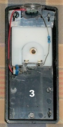
Photo 2
Photo 3
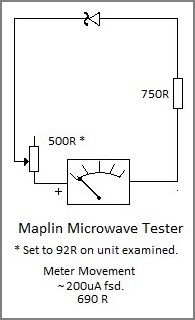
The picture to the right shows the Maplin Microwave Detector with the rear cover removed. The working components are few and simply soldered together. A small printed circuit board is used mainly to hold a surface mount schottky diode and provide suitable solder pads for hand assembly. The three component circuit is shown left and requires no battery supply.
The resistor and wiring is used as an aerial to pick up the 2.4GHz radio oscillations at close range. The diode allows the absorbed current flow in one direction only and this moves the meter needle proportionally across the scale.
<<<<<The circuit is drawn showing the same positioning of the parts in photo 3.
Although the specification quotes a frequency range of 3 Megahertz to 3 Gigahertz, the response to 27, 35, and 40 MHz model transmitters is very low with barely any deflection at all. For this reason the detector is not suitable for older frequency transmitters. One exception was use alongside the aerial loading coil on a 35MHz micron transmitter where almost full scale deflection was obtainable.
It must be remembered the ‘Maplin Microwave Leakage Detector’ is simply that!! It has been designed and pre-set by the factory to detect microwave oven acceptable levels of leakage, usually from the door joints and it does this using extreme simplicity of parts. Good design is always simple. Its use for testing radio control transmitters just happens to be one of its other possibilities.
Although it’s been demonstrated above that the Maplin Detector can be used for a quick check of model control transmitters, the design appears to be capable of further development for the Radio Control environment and in the near future we may come up with a few ideas. Possibly reader ideas too!
One simple idea tried was shorting the 750R resistor with copper wire and removing the 500R trimpot (red wire solder direct to meter +). This gave Full Scale Deflection of the meter needle in Photo 2 above.
A simple air compressor for airbrushes using a car tyre inflator…………
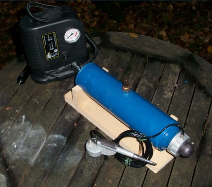
The tank is an empty butane/propane canister used for a blow torch and ready to be chucked away. A brass Schraeder car tyre valve has been sweated (flow soldered) into the end of the can. A standard 12volt car type tyre inflator is connected to the end of the canister. These inflators provide pulses of compressed air. The canister stores these pulses and smooths them out under pressure providing a smooth airflow to the airbrush.
A simple ‘blow off’ safety valve was cobbled up using a ball, spring, screw device which has now been set to 30psi which seems about right. This safety valve unit was also soldered into the outside of the canister at the top as shown.
As the ‘DSL’ make (Automobile Association) car tyre inflator was already available in the boot of the car and the other bits were laying around ready to be chucked out, David produced this effective working machine at a total cost of Nowt ! Total time involved was just one day. As you can see it must have been quite a full day as it was dark when the picture was taken !
ONE OF ROB GREEN’S LATER PROJECTS IS A MODEL OF THE MAGESTIC AVRO VULCAN.
This one is based on the very last full size flying example.
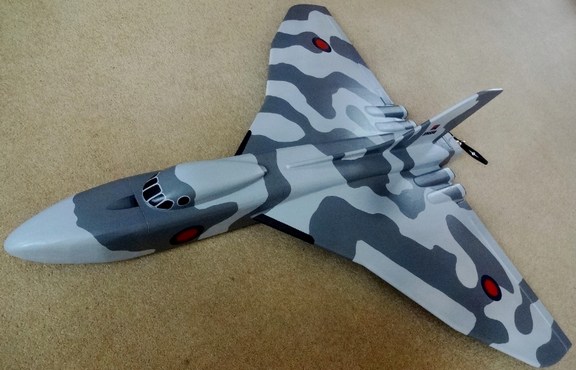
‘It has not yet taken to the air as I am going to change the prop to a folding type to prevent prop damage on landing.
Although a war machine I think the wing shape is classic and so attractive.
The registration number belongs to the very last flying example of the 70 ton beast which cost £24,000 just to refuel.
Mine costs £15.00 for one 3S 2200 mAh battery so much cheaper to run. (RG)’
An early model of the Avro Vulcan 707a is mentioned on page 8 of this site. Construction in those days (60 years ago!) involved carefully cut balsa bulkheads with balsa wood stringers forming the fuselage. The wing construction being very similar with stringers over carefully cut different size wing ribs forming the classic delta shape. The quick drying glue in those days was called ‘Balsa Cement’. (a thickish cellulose base product in tubes). The whole model then being carefully covered in tissue paper using ‘tissue paste’ (similar to White Glue of today). A clear ‘thin’ cellulose paint mix called Dope was then applied. This stuff dried in in about 15 minutes, shrinking the tissue paper as it did so. After a couple of coats of Dope the model looked surprisingly crisp and shiny and no wrinkles. The resulting structure was not capable of heavy landings however, and things like small screwdrivers, model knives, etc, in your top shirt pocket would simply fall through the tissue covering as you kneeled over the model.
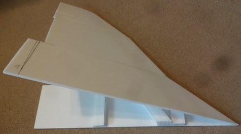
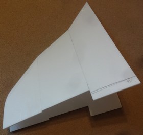
Construction details of Rob’s E-Vulcan follows showing the vastly different techniques used….
The wing construction is of particular interest in that it is hollow and folded at its leading edge in three separate units which are finally joined together to form an impressive shape. (see pictures).
My build was finished using glass cloth to toughen the surface which increased the AUW to 1250g so be prepared to adjust your power unit accordingly.
Gaham Dorschell can be found here for the more ambitious builder
http://www.gibbsguides.com/article24_Vulcan_EDF_Part1.htm?,_Avro_Vulcan,_New_Lipo_Guide
And here for the plans of the Depron 'easier build'
https://www.sarikhobbies.com/product/e-vulcan-plan/
To date I have not flown mine due to the weather but it has been an interesting journey and I hope I have inspired others to build this iconic air craft.
Specification :-
The Vulcan I have recently built known as the E-Vulcan (electric) is as follows ...................
Pusher sport scale
5mm-6mm Depron
42" wing span
40" long
900g approximate AUW
1250 kv out runner
60amp esc
8"x6" pusher prop
3S 2200-3000 mAh LiPo
c of g 8.75" from LE
Designed by Gaham Dorschell.
Rob Green is often seen flying over the Berkshire Downs at the Hungerford Model Flying Club
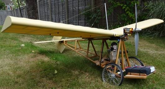
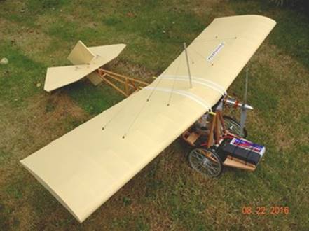
Rob continues with some construction detail of his Model of the 1909 Monoplane ‘DEMOISELLE’
The Santos-Dumont Demoiselle was a series of aircraft built in France by Brazilian aviation pioneer Alberto Santos-Dumont. They were light-weight monoplanes with a wire-braced wing mounted above an open-framework fuselage built from bamboo. The pilot's seat was below the wing and between the main wheels of the undercarriage. The rear end of the boom carried a tailwheel and a cruciform tail.
Part 1
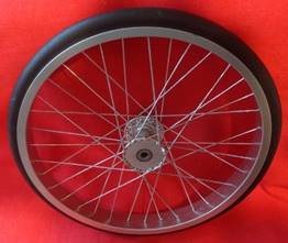
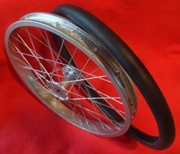
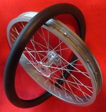
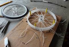
CONSTRUCTING 6 1/2" WHEELS (45grams each, incl tyres) FOR MODEL DEMOISELLE
Originally designed & Built 1909 by Alberto Santos-Dumont (1873-1932)
Replica (1999) can be seen @ Brooklands Museum Surrey England.
The ¼ (part) scale 50” wing span model was featured in Quiet & Electric Flight International magazine January 2013.
Having decided to build a ¼ part scale model of the 1909 monoplane I opted to start with the wheel construction, beginning with the wheel jig comprising of a flat wood base appropriately drilled for the centre steel axle and rim supports also in steel. The Perspex/plastic wheel hub, later turned on the lathe, is placed into a recess over the centre steel support, allowing the finished wheel the desired amount of shape when viewed in profile. The rim was made from Perspex/plastic 6” diameter tube (Ebay) of sufficient thickness to allow it to be turned down on the lathe and form a ‘tyre well’.
The 36 holes were drilled in the rim simply by wrapping one revolution of masking tape around the tyre well, followed by its removal, lying out on a flat surface and measure out the increments, replacing the measured tape and drilling free hand.
The hub spacing was achieved by establishing a centre point and drawing out, on paper, a large circle divided into 10 degree spacing giving 18 holes to drill each side of the hub flange once transferred to the hub.
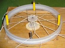
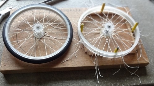
The rim and hub are placed onto the board ready to ‘thread up’ with ‘Spectra’ (minimum stretch) kite line. At this point I opted to copy a bicycle wheel in terms of spoke orientation, which was a great help in achieving a good outcome. Here is where we make use of the ‘slip knot’ (see internet) after threading the first rim hole from the outside pass it through and over any hub hole and under to the 6th hole position to the left, pulling up through this hole and back to the 3rd rim hole to the right. It is here that the slip knot is formed, leaving one thread longer when cut off, thereby allowing further tightening of the ‘spokes’ later on by way of the slip knot. Repeat this operation on the opposite side of the rim (90 degrees to starting point) followed by repeats every 90 degrees until fully laced.
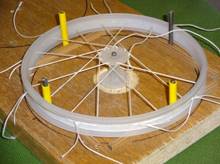
Flip the wheel over on the jig and repeat the threading routine until complete.
You will now have 36 double thread ends (72 thread tails), each pair will have one chosen thread cut longer, which will identify the one needed to tension before cutting off.
Spin on a shaft and tension the tails until the wheel runs reasonably true.
The finished tails are then cut off and ‘fixed’ with super glue to prevent loosening.
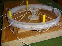
Neoprene round section foam seal was used for the tyres, cut & super glued as a butt joint, followed by ‘grinding’ a groove to accommodate the ‘thread’ ends remaining in the tyre well.
Apply x 2 coats of silver from an aerosol spray can to finish.
Practice will be seen to make perfect during this procedure, followed by a great sense of achievement when completed.
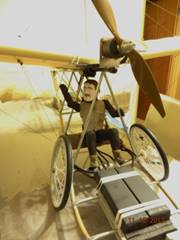
COMPLETED DEMOISELLE … frame work – 12mm dowel … LiPo’s mounted forward of axle to balance.
Part 2
¼ SCALE DEMOISELLE WELDED ALLUMINIUM ALLOY FUSELAGE FRAME WORK CONSTRUCTION
Model plans taken from Quiet & Electric Flight International magazine January 2013.
The original 1909 Demoiselle used bamboo for its fuselage construction.
For this model I chose to experiment using aluminium tube intended for the construction of full size microlight air frames, used by me years ago in the construction of large kites to carry camera equipment. (Before digital cameras & drones ……. another story)
Later I used Ramin dowel as a replacement frame work owing to extensive flight damage caused by a failure in the closed loop elevator control system.
The model is 50” (inches) wing span & flies very well (rudder/elevator/esc)
Once the tube components are cut and shaped to size proceed to assemble in stages using twisted (tensioned) wire and homemade aluminium or/and (wood if @ distance from your flame) clamps.
The weld rods I used were ‘Techno- Weld Ltd’ but please read all safety and technique guides whichever product you choose to use for your particular application.
The welding technique used was enabled by using a mixed butane/propane gas torch with a fairly broad flame with medium blue centre cone, mostly concentrating the flame on the thicker parts thereby allowing conduction to heat the thinner parts which might otherwise suffer overheating and subsequent melting. There is no need to rush or panic this operation because the weld rod tip will tell you when you have reached the required temperature by simply repeatedly introducing it to the framework, the tip of the rod will begin to melt (outside the flame envelope) when the ideal temperature is reached, followed by the use of a stainless steel tool (wire or pointed instrument) to abrade the tube surface and break through the layer of oxidation enabling penetration. So the key to success is not to overheat the thinner portions but to ‘play’ your flame on thicker parts, gradually allowing the heat to transfer to thinner sections so long as they are close fitting.
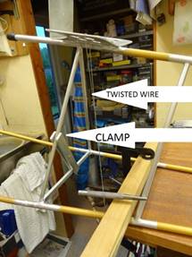
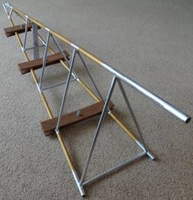
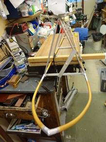
Use of scrap wood & aluminium clamps, centre bolted, to aid the welding process. Twisted soft wire
also helps secure tubing during the welding process.
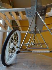
Note….. Home made spoked (kite line thread) wheels.
(see above for more detail)
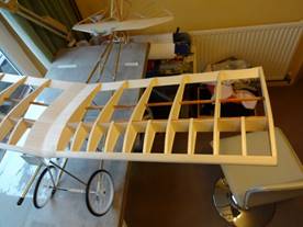
Framework, wheels & axle nearing completion prior to wing covering.
(front battery section to be added).
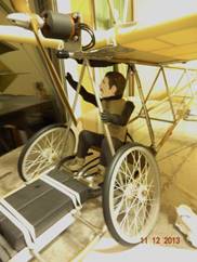
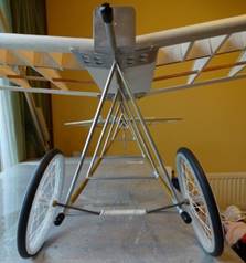
Photos of the completed Aluminium frame version.
Wood frame version.
Completed airframe with seated foam pilot.
Thanks for looking and good luck with your first aluminium air frame.
Rob G. Feb 2018 
 norcim-rc.club model radio
control history and electronics.
norcim-rc.club model radio
control history and electronics.
![]()