
Page 23
![]()
![]()
![]()
It is technically possible to fit an aftermarket aerial (antenna) to your radio control transmitter which would at least double the range!!.. Now not a lot of people know that! OK, if that’s the case, why aren’t we all using these things and why don’t the manufactures include these devices as standard?
Well one thing is, the aftermarket antenna is quite directional, so you would have to keep the Tx antenna ‘looking’ at your model for best range. Another problem is when your Tx is ‘by chance’ looking at another model in the sky, then your signal could be five or six times stronger than its parent transmitter and at range this could cause problems.
Reader and contributor Robert Coggan explains the detail……
 Robert Coggan is a consulting engineer and professional designer
of electronic circuits.
Robert Coggan is a consulting engineer and professional designer
of electronic circuits.
Robert’s Email content that follows explains the legal technicalities of the UK position relating to aftermarket antenna systems for radio control models in much more detail…….
EIRP (Effective Isotropic Radiated Power)
seems be to widely misunderstood but it is commonly used in radio transmission
to define the maximum radiated signal in a given direction. As you have found
out by experiment, it is quite difficult to measure the polar output from an
antenna due to all the ground reflections etc. As an alternative, it is more
practical to measure the transmitter's conducted power i.e. the power from the
electronics which feed the antenna, than add the antenna gain. You simply
unplug the antenna cable and connect the transmitter output direct to a
suitable power meter or spectrum analyser. Knowing this, you simply add the
antenna gain to get the final eirp. This will then
define the maximum power being radiated in a specific direction relative to an
isotropic antenna. Many of the transmitter antennas are half-wave dipoles which
have a fairly well defined gain of 2.15dBi. I've attached a useful document
from the FCC which gives some practical advice about measuring eirp.
I often use a light bulb analogy to explain this to the non-technical masses
(most of the UK these days). A light bulb is a bit like an isotropic antenna,
radiating it's power equally in all directions. Suppose you have four people
standing close together in the pilot's box each transmitting with a different
coloured light bulb, say red, green, blue and yellow, but all with the same
power. Your plane's receiver only decodes the red signal, so imagine you are
across the field, a couple of hundred feet up looking back at the pilot's box.
You will see four equally bright bulbs, but it isn't too difficult to pick out
the red one and you focus on decoding its signal. This will be the same
wherever you fly in the field as all bulbs are radiating equally in all
directions.
Now suppose the guy with the yellow bulb decides to fit a parabolic reflector
behind his bulb (as in a torch). This focuses much more of the power forward to
boost the radiated power in that direction. Looking back from the plane and you
will now find that when you fly across his beam it will harder to see your red
bulb because his yellow one is glaring brightly at you. The overall bulb power
remains the same, but the signal in a given direction (power density) has increased
significantly. Spread spectrum technology is very good at dealing with these
situations, so it might not cause other receivers to lose signal completely but
it will certainly reduce margins.
Thinking about it, this is one of the reasons why we all stand close together
in the pilot's box - all receivers in the air will see roughly the same signal
coming 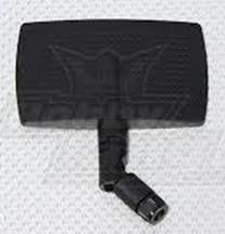 from all transmitters, giving each the best chance of decoding its
own good signal.
from all transmitters, giving each the best chance of decoding its
own good signal.
Adding a reflector to the back of the bulb is a bit like adding a reflector to
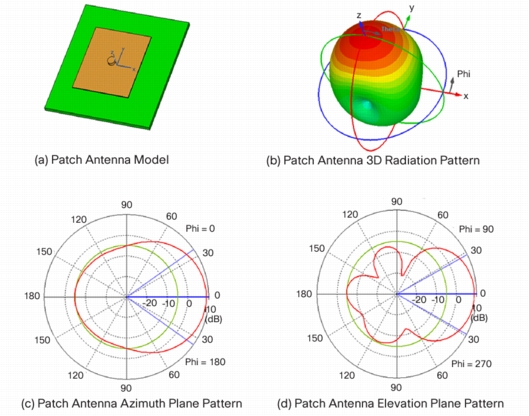
the dipole creating a 7dBi "patch" antenna, like one of these:- (see
picture to the right). This one is a Hobbyking Patch
Antenna.
They are more directional and have a forward gain of 6 to
8dBi i.e. around 5dB (3x) more than the dipole. This will increase eirp from 100mW to 300mW which is not legal in the UK -
I've attached a copy of Ofcom's document which gives a simple but comprehensive
explanation of the UK situation. Incidentally, Ofcom did review my article for
BMFA News for technically accuracy, and it passed!
Does it matter? Well, compare it to the noise limits that we adhere to. The
recommendation is 82dBA max, but increase this to 87dBA - "whoa, you can't
fly that here, mate, too noisy." The only difference is, you can't hear
2.4GHz.
The narrower beam width of patch antennas causes an additional problem. Let's
first have a look at the polar plot for a dipole (courtesy of Cisco):
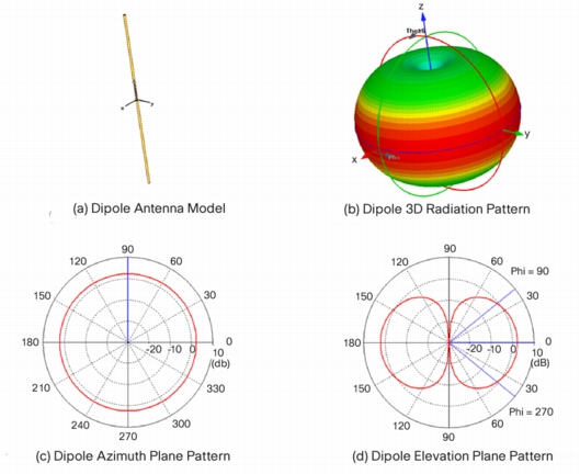
You can see from the azimuth plot that the dipole has a
constant +2.15dBi gain all around i.e. omnidirectional.
Compare this with a typical patch antenna:
The forward gain along the 0deg axis is about +8.8dBi, but
reduces to 0dBi at +/-65deg off axis, and -5dBi at +/-90deg. In other words,
the patch is about 7dB worse than the dipole on either side, and guess where
most people fly furthest from themselves - yep, to either side. I'm sure it's
no coincidence that down at the field I see more planes come down due to
"radio problems" on either side than anywhere else. I wonder why -
"must be some interference out there", "don't trust this 2.4
stuff"..............Hmm.
The other thing that folks don't realise is 2.4GHz suffers much greater signal
attenuation compared to 35MHz. Just check out the Friis
transmission equation - the signal falls not only as the inverse square of the
distance but also as the square of the wavelength - it's quite frightening.
Spread spectrum techniques really do work well at receiving very small signals,
they have to.
http://norcim-rc.club/Radio23_files/image009.jpg
This is a very big subject, and gets extremely complex when you get into all
the maths, but simple common sense rules will give a reliable radio
installation. I think the plug & play nature of 2.4GHz radios has led to a
lot of complacency with many installations running close to the edge. Folks are
unwittingly relying on ground reflections to maintain an adequate signal, but it
doesn't take much to push the signal below the threshold and trigger
"failsafe".
There are some relatively inexpensive Tx Output
meters out there that can do a simple check. I guess they not only find the
villains who have slipped a 1W amplifier inside their tranny, but also gives
reassurance that an adequate signal is actually being transmitted -
essential for safety at large public events.
Regards
Robert Coggan
Many Thanks to Robert for the detail above with
some brilliant graphics and down to earth presentation of the heavy technical
detail involved. Obviously a true R/C modeller with the ‘Know How’. There few
about with this background!
A commercial version of a parabolic
directional antenna that has recently become available (April 2021) is shown at
the bottom of this page. It is claimed to give 3.5 Km range.
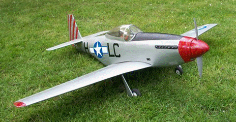
NOW BACK TO THE FLYING MODEL SCENE…with one of David Caudrey’s early scale slope soaring aircraft. It’s a Mustang which flew well in days gone by. Recent thoughts however have led to fitting a brushless electric motor with suitable prop.
 <<The picture to the left shows
the Mustang just before the conversion to electric began. Existing Servo
controls have been kept the same with full length aileron, elevator and rudder.
A forth channel will now be used for motor control. The Mustang has full span
ailerons and an undercarriage is now fitted including tail wheel. The rear half
inch of the spinner is static, housing the motor support.
<<The picture to the left shows
the Mustang just before the conversion to electric began. Existing Servo
controls have been kept the same with full length aileron, elevator and rudder.
A forth channel will now be used for motor control. The Mustang has full span
ailerons and an undercarriage is now fitted including tail wheel. The rear half
inch of the spinner is static, housing the motor support.
The model flew beautifully as a slope soarer but the Hampshire diamonds (flints) gauged the soft balsa air intake under the fuselage on landing so I didn’t fly it very often. To give some idea of the own design size, the span is 48” which is 0.125 scale. I built it because PSS scale was popular at our site in the 1990s and the ARTF commercial versions were a travesty of the real aircraft. It was designed at work during lunchtime.
 The next picture to the right>>>>>> shows the finished conversion to electric. Note the undercarriage
along with a tailwheel which can’t be seen.
The next picture to the right>>>>>> shows the finished conversion to electric. Note the undercarriage
along with a tailwheel which can’t be seen.
The Mustang has a JP 600/0/R 1100/ (C35-14) motor fitted.
This will give more than enough power as I intended to swap it with the JP 500
in the Puppeteer which could do with a little more. However the 600 equivalent
motor won’t go between the bars of the welded aluminium motor mount for the
Puppeteer (see page 20 for detail of the motor mount)
so the Mustang gets the more powerful one. The ESC for both models is the
JP Pro 50 SBEC. The Mustang is intended to be powered by a 3 cell 1800/2200
battery but I might fit a larger diameter prop and use 2 cells for initial
flights. The prop 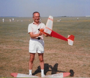 shown
is an 11”x5.5”.
shown
is an 11”x5.5”.
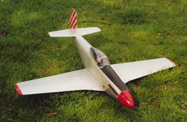
<<This picture goes back to the 1990’s showing flying friend Ian Kirkpatrick who helped with the flying of all David’s free flight models and later R/C versions, many of which were David’s own design. The free flight model shown is a ‘Keil Kraft Outlaw’. The motor is a DC Sabre 1.5cc.
There is little doubt that electric flight is a heavier installation in a model compared with diesel or glow motor when you consider the battery weight. Also unlike diesel or glow fuel which gets lighter towards the end of the flight, assisting landing, the flight battery weight remains the same when flat. The noise of electric flight can be made to be very quiet which is more acceptable if flying close to housing. (Obvious exceptions include ducted fan and aerobatic aircraft). Diesels and glow motors are noisy and dirty by comparison. Odd really when some 1000cc motorbikes can be quieter!
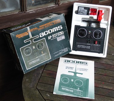
Latest donation from a member of the Hungerford Model Flying club to David C is an estimated 35 year old two channel Acoms radio control system.
Acoms problem began with the introduction of UK 35MHz. Acoms was an AM system well capable of 10KHz spacing on 35Mhz but FM receivers didn't like AM Transmitters around them. They would jitter their servos. The average modeler concluded that Acoms was 'Dirty' and kept a couple of channels away from an Acoms Tx. I think another manufacturer also used AM at the time. Nothing was in the initial regulations to say that only FM should be used. Looking on a spectrum analyzer the Acoms 35MHz AM signal was squeaky clean and easily passed 10KHz spacing. It was the FM receivers problem really but Acoms got the blame. The FM brigade won in the end and the 35MHz FM band became FM only.
FM systems actually started back in the 27MHz days before 35Meg was introduced to the UK. The first Micron 27MHz FM receiver used an AM type front end (which was readily available) i.e automatic gain control and transistors. The second board used an FM decoder chip (TD???) and the usual 4017 chip servo output. SLM made the plastic case for it. This early Micron FM reciever worked without any problem at all alongside AM transmitters of the time. The use of AGC circuitry allowed this to happen. The receiver was however relatively large and Micron turned to dedicated FM receiver chips for later receivers.
If
the ‘Keil Kraft Outlaw’ above ever changes to
electric Free Flight then the DIY timer here may help….
 Doc5
Doc5
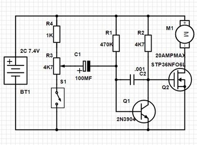
A POSSIBLE 10 TO 30 SECOND ELECTRIC FLIGHT
TIMER CIRCUIT for free flight model aircraft.
Inspiration for this circuit design came from
Ian Kirkpatrick (see page 23 of the Norcim website).
The model electric flight motor is connected to the Lipo
2C battery via the circuit with the switch in the off position. At the point of
‘switch on’ the flight motor will run for a time depending on the position of
the variable resistor setting. This should be between ten and thirty seconds.
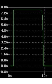
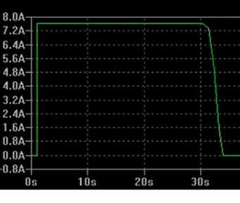
FLIGHT TIMER
CIRCUIT
LTspice
SIMULATIONS
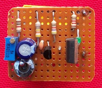
<< PROTOTYPE USING STRIPBOARD
The circuit gives instant motor at ‘switch
on’ with a ‘soft’ switch off of around 1>2 seconds which will help prevent a
stall. Increasing C2 would make the switch off softer. Assembly using
strip-board. Note if R4 = 100R will give 0 to 30 seconds motor run. The circuit
also works well using a single cell Lipo battery. The
timings appear to be the same.
The large UK following of Free Fight Model
Aircraft can be seen at. Sam1066.org
NORCIM-RC 03/17
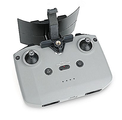
The photo
right, refers to Robert Coggan’s technical input at the top of this page where
he outlines the use of a possible 2.4 GHz directional aerial. This one is
available now (April 2021) costing around £15 and can be fitted to a DJI Mavic
2.4 GHz transmitter.
The
reflective panel is simply pointed in the direction of the model which will
give a stronger signal to the receiver.
An independent
test claims a range of 3.5 Km is achievable.
Thanks for reading…