TOP

Norcim rc electronics
club page 20……
![]()
![]()
![]()
SOME USEFUL LINKS ![]() HobbyCity
HobbyCity
![]() GreatHobbies
GreatHobbies
![]() BangGood
BangGood
![]() ModelFlight RC
ModelFlight RC
![]() HorizonHobby
HorizonHobby
FURTHER
RADIO CONTROL ELECTRONICS NOTES.
This page is started by Georges Bery from Switzerland with some interesting DIY transmitter designs:
Dear Terry,
Bit of bragging is in order here.
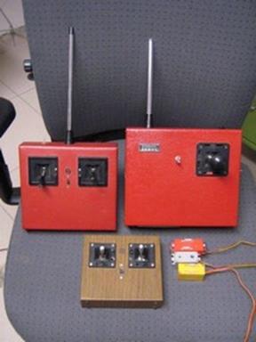
The pick with 3 transmitter contains : two 2 stick units built around 1984/5 and the single stick is 1989 vintage. ne5044 encoders with Terry Platt RCM&E RF section. SLM stick for the two red ones, the woody has nondescript Chinese stick . The 3 axis was purchased from lextronix in Montfermeille .
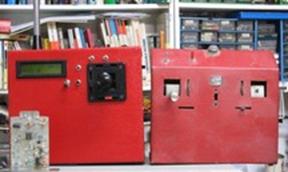
The one called microstar contains The reworked single stick with a microstar encoder job finished 2011 and my very first transmitter 1979 vintage, Cmos encoder 5 channel and plug in RF modules according to the TF6 standard published by Francis Thobois in le Haut parleur. It allowed me to swap frequency in those troubled times of CB pirates and go from 27Mhz to 40 then to 72 and 35 AM and FM.
Same system used in the single stick with next to it one of the RF decks. (with a VN46 Vmosfet )
Being born in a wee country that gets occasionally trampled upon by almost all its bigger neibours has not only disadvantages, it allowed me to get my hands on most RC and electronic magazines of the period : French-German-British-American- Dutch. And very rich they were in such projects all of them.
 I have kept most of them so if you’r
looking for something 1977-2003 period I have most . After, either they ceased
to exist (RCM, le hautparleur,radio plan, ETI,
practical electronics,…..) or I couldn’t be bothered by RTF reviews or 2.4Ghz WiFi based Chinese plastic junk.
I have kept most of them so if you’r
looking for something 1977-2003 period I have most . After, either they ceased
to exist (RCM, le hautparleur,radio plan, ETI,
practical electronics,…..) or I couldn’t be bothered by RTF reviews or 2.4Ghz WiFi based Chinese plastic junk.
Current effort is in an Ace commander single stick case with Kraft stick and SLM button, with futaba 35Mhz synthetized rf deck and M*2K encoder. It is visible in 3d pic.
 Sorry
for being immodest but hey, that’s also part of the hobby !
Sorry
for being immodest but hey, that’s also part of the hobby !
Best regards
Georges
Thanks for the input Georges !...as you can see it has got us all thinking now about
‘Single Stick’ control and where and why did it get buried ?
Georges Bery’s range of home brewed transmitters brings back many happy memories in Micron days trying prototypes of triple axis stick transmitters. Having grown up with early pulse proportional systems that used just one control stick (Galloping Ghost), for rudder and elevator control, the search for increasing the number of controls to throttle etc inevitably grew around that single established joystick. In those early days, any additional controls to the model were simply ‘add-ons’ to the already established ‘single stick’. Throttle control was the first to come and usually involved a small lever on the Left side of the transmitter or a couple of buttons to give Hi or Low throttle. Development then progressed around that established ‘single joystick’ to allow Left/Right movement to give aileron control. Push Forward, for down elevator, Pull Back for up elevator. And TWIST the joystick clock or anticlockwise to effect Rudder movement. This ‘new’ development was called a Triple Axis Joystick and remained for a short period with many transmitter manufacturers.
 Triple
Axis Transmitters however had a few ergonomic problems. (1) They were normally only
available for right handed people. (2) Holding the transmitter with the only hand
left, presented a problem. Often a neck-strap helped with this. (3) Where to
put the throttle lever ??. Often it was put on the front LHS of the case with a
neck-strap used to support the transmitter. Several users however preferred to
‘cuddled’ the Tx box with the left arm, with the
right hand fingers/thumb on the top of the joystick. So the throttle lever had
to be where the left hand fingers were. i.e on the
right side of the ‘Box’ somewhere.
Triple
Axis Transmitters however had a few ergonomic problems. (1) They were normally only
available for right handed people. (2) Holding the transmitter with the only hand
left, presented a problem. Often a neck-strap helped with this. (3) Where to
put the throttle lever ??. Often it was put on the front LHS of the case with a
neck-strap used to support the transmitter. Several users however preferred to
‘cuddled’ the Tx box with the left arm, with the
right hand fingers/thumb on the top of the joystick. So the throttle lever had
to be where the left hand fingers were. i.e on the
right side of the ‘Box’ somewhere.
Now considering that, these transmitters should also be available for ‘Lefties’ with their different preferences of throttle…….You can see that multiple production presented problems.
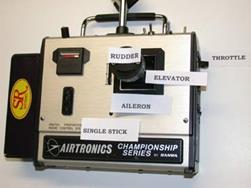
Note, the picture to the left shows a typical ‘Single Stick’ transmitter. This one is a ‘cuddle’ type for Right Hand users only. Much more information is available at the original website. written by Bob Aberle. http://www.modelaircraft.org/mag/FAQ/answers/faq-q31.htm Well worth a visit. (What’s that black thing on the side of the Tx ?)...well you will have to pay a visit to the website above !
Some bright spark however rapidly produced a solution. Simply put two Dual-Axis joysticks at the top front of the transmitter case ! Get the fliers to use ‘thumbs on top’ of the sticks and (lefties included) could sort out which control movement was best for them. The transmitter in this way was securely supported with both hands without the need for a neck-strap.
It is interesting that well after the marketing and acceptance of the ‘standard’ two joystick R/C transmitter, some USA model aerobatic championship fliers were still using ‘Bespoke’ Three Axis Joystick transmitters.
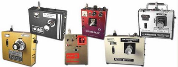 Probably
the best website for ‘Single Stick’ radio
control history is Duie Matenkosky’s
website http://www.singlestickstuff.com
Duie shows his collection of six working transmitters
along with lots of background history. Duie still
flies ‘Single Stick’ and has done for 30 or forty years ! His website is
professional and very thought provoking about why this form of control layout
appears to have got left behind. It is the nearest thing to the controls of
full size flying.
Probably
the best website for ‘Single Stick’ radio
control history is Duie Matenkosky’s
website http://www.singlestickstuff.com
Duie shows his collection of six working transmitters
along with lots of background history. Duie still
flies ‘Single Stick’ and has done for 30 or forty years ! His website is
professional and very thought provoking about why this form of control layout
appears to have got left behind. It is the nearest thing to the controls of
full size flying.
Duie Matenkosky’s collection of ‘Single Stick transmitters >
(Much better to visit his website above)
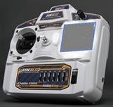
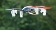 I have two of the readily available
Quadcopters (Drones). Both supplied with the ‘normal’ R/C
transmitter layout, (two dual axis stick units). I am totally convinced that if
a ‘Single Stick transmitter’ version was available for these
machines, then control of them would be so much easier for the hobby flier.
Movement Left and Right….Forward and Backwards seems to be mastered without too
much time being involved but mixing this with correct direction of flight takes
some practice with two sticks. The rotary bit of the ‘Single Stick’ would make
life much easier with drones.
I have two of the readily available
Quadcopters (Drones). Both supplied with the ‘normal’ R/C
transmitter layout, (two dual axis stick units). I am totally convinced that if
a ‘Single Stick transmitter’ version was available for these
machines, then control of them would be so much easier for the hobby flier.
Movement Left and Right….Forward and Backwards seems to be mastered without too
much time being involved but mixing this with correct direction of flight takes
some practice with two sticks. The rotary bit of the ‘Single Stick’ would make
life much easier with drones.
 David
Caudrey rummaged
around the stuff that one collects with a lifetime in this hobby and came up
with, ‘Would You Believe It’, A (‘Single Stick Joystick !). Well, to be
‘mechanically’ correct , should we really call it a Triple Axis Joystick’? …Well,
if there is a possibility of ‘Single Stick’ control layout for model Radio
Control transmitters re-
David
Caudrey rummaged
around the stuff that one collects with a lifetime in this hobby and came up
with, ‘Would You Believe It’, A (‘Single Stick Joystick !). Well, to be
‘mechanically’ correct , should we really call it a Triple Axis Joystick’? …Well,
if there is a possibility of ‘Single Stick’ control layout for model Radio
Control transmitters re-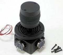 inventing
itself, then perhaps we should start by using the terminology of the industry
which are presently using thousands of these things annually. The Games and
Robotics manufacturers have found the obvious advantages with these joysticks
as well as the Space and general industrial applications.
inventing
itself, then perhaps we should start by using the terminology of the industry
which are presently using thousands of these things annually. The Games and
Robotics manufacturers have found the obvious advantages with these joysticks
as well as the Space and general industrial applications.
Unfortunately, the ‘Industrial’ specification comes at a cost and although readily available, the present breed of analogue Triple axis Sticks are expensive for use by model radio control manufacturers. I will include just one of the superb triple axis industrial versions here that sell in their thousands. (see Right picture)>>>>>>>>
The upper image of David’s findings we have little idea of origin. To us it looks a Skyleader possibility or perhaps an early fleet Transmitter. Without doubt, it was not used by ‘Flight Link’ as they manufactured their own design triple axis stick system which was to be honest, mechanically very professional. I have an urge to get David’s findings into an existing transmitter that I have lying around and see if I can re-live the unique feeling of being part of the model !
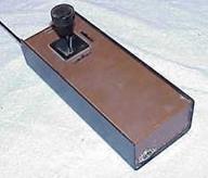 The picture to the left shows a fairly rare example of just one of many Heathkit’s radio control transmitters available
around 1970ish. YES ! it’s a triple axis stick version, or should we say
Single stick ? Either way, this unconventional shape and narrow
dimensions allowed either hand to securely hold the transmitter case. Now,
with a slider control conveniently positioned for thumb use on both
sides of the case, throttle and one extra channel could be available for both
RH and LH users. This basic layout does get around ‘the ergonomic problems’ mentioned
above allowing quantity production to suit all model and drone fliers.
The picture to the left shows a fairly rare example of just one of many Heathkit’s radio control transmitters available
around 1970ish. YES ! it’s a triple axis stick version, or should we say
Single stick ? Either way, this unconventional shape and narrow
dimensions allowed either hand to securely hold the transmitter case. Now,
with a slider control conveniently positioned for thumb use on both
sides of the case, throttle and one extra channel could be available for both
RH and LH users. This basic layout does get around ‘the ergonomic problems’ mentioned
above allowing quantity production to suit all model and drone fliers.
With a quality plastic case, click type in-flight trims, LCD display and 2.4 GHz, Mmmm, could this be a possible way forward for manufacturing designers of a future Single Stick R/C Transmitter ? (see very rough sketch right) >>
http://www.superdroidrobots.com/shop/item.aspx/analog-3-axis-joystick/1263/
http://www.p3america.com/joysticks_text.htm?gclid=CID5z_Lxq8ICFXQatAod4goARg
May the ‘Single Stick’ be with You !
 LAPTOP TOUCHPADS ARE BEING
TRIED IN PLACE OF R/C JOYSTICKS. Although difficult to get any technical information or pictures
about this development, at least one R/C manufacturer has been involved in the
development of an electronic joystick. Making use of a modified laptop
‘Touchpad’, it has no moving parts. Moving the thumb on the pad produces a
similar effect to a normal dual axis joystick. Lifting the thumb from the pad
returns the servos to centre within 10 milliseconds without the several
rebounds of the mechanical type. Swiping the outside edges of the pad produces
in-flight trims. (each swipe, giving just one degree movement at the servo).
Automatic in-flight trim is said to be a possibility and could probably be
installed in the production versions.
LAPTOP TOUCHPADS ARE BEING
TRIED IN PLACE OF R/C JOYSTICKS. Although difficult to get any technical information or pictures
about this development, at least one R/C manufacturer has been involved in the
development of an electronic joystick. Making use of a modified laptop
‘Touchpad’, it has no moving parts. Moving the thumb on the pad produces a
similar effect to a normal dual axis joystick. Lifting the thumb from the pad
returns the servos to centre within 10 milliseconds without the several
rebounds of the mechanical type. Swiping the outside edges of the pad produces
in-flight trims. (each swipe, giving just one degree movement at the servo).
Automatic in-flight trim is said to be a possibility and could probably be
installed in the production versions.
Availability of two stick transmitter versions is aimed at early April 2015.
May the Happiness be with you !
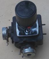
 ORIGINALLY BOUGHT FOR CARAVAN USE, CHARGING BATTERY FOR
LIGHTING AND 12V TELEVISION, THIS PETROL GENERATOR ALSO SUPPLIES A 240V OUTPUT
SUITABLE FOR LAPTOPS AND SENSITIVE ELECTRIC FLIGHT CHARGERS.
ORIGINALLY BOUGHT FOR CARAVAN USE, CHARGING BATTERY FOR
LIGHTING AND 12V TELEVISION, THIS PETROL GENERATOR ALSO SUPPLIES A 240V OUTPUT
SUITABLE FOR LAPTOPS AND SENSITIVE ELECTRIC FLIGHT CHARGERS.
The IMPAX 800 is quite light and easy to carry. Two litres of petrol will last all day and with a multi-mains extension socket will power up to six fast chargers at the flying site. Running with the economy switch is just 1800 RPM, almost tick-over speed for this 60cc Rapier engine. So noise level is low. Up against the fence of your flying site, you will never hear it whilst flying. The internal technology uses many magnets on the rotating crankshaft to produce healthy DC volts (rectified) which drives a sophisticated inverter circuit producing a very controlled, pure sine-wave 240 volt AC output. In many respects, it compares favourably with the Honda portable generator presently available in the UK retailing at £820. This little Gem is readily available, UK wide for just £189. Ideal for R/C club use! The picture shows the control panel of the charger and the exhaust end. Also with a side panel removed, shows the compact layout of air filter, carburettor, oil filler plug, and large effective exhaust silencer. Obviously, of Chinese manufacture but the Chinese technologists and manufacturers probably lead the world of technology at the moment. If you want quantity ‘cheap and cheerful’ products, then they can supply. On the other hand, if you want a high quality product, in quantity (which this generator certainly is), then these Guys are certainly capable. The same generator is available using different names and colour in Australia, America and Canada.
 ARE DIESELS AND GLOW
MOTORS NOW A DYING BREED FOR MODEL AIRPLANE ENGINES?
ARE DIESELS AND GLOW
MOTORS NOW A DYING BREED FOR MODEL AIRPLANE ENGINES?
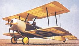
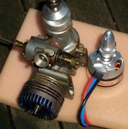
David Coudrey is at the moment renovating a gift from a flying friend. Namely a Flair ‘Puppeteer’. One major intension is to change the existing Super Tigre 40 with an equivalent power brushless motor. The picture to the left shows the significant difference between the IC motor and the Electric replacement. The electric motor body is less diameter than the ST40 crankcase, much less length to the prop driver and no carburettor or piston, cylinder, glow plug. There is no need for a silencer too.
It is easy to see how ‘Electric Model Flight’ has progressed over the last three decades. David went into some of his usual simple scientific stuff coming up with the fact that this conversion would save 327gms (11.5 ounces!)
Against the equivalent conventional Glow Motor power propulsion system.
Weight of IC combo – ST40 + silencer + throttle servo + 10 x 5 prop + half full 6oz fuel tank + Rx battery 2300mah = 697 g.
Weight of electric motor + 5O amp ESC + 2200 3 cell Lipo. (30C) + 10 x 5 prop (electric) = 370g
To give an idea of this in simple terms, it means that 40 US Dollar coins or 34 UK pound coins would have to be used as ballast in the front cowl, around the electric motor to bring the model back into correct Centre of Gravity trim for stable flight ! However, David is working on shifting the electric bits forward to drastically reduce this necessity for ballast. We, Will keep you informed of progress!….
OK..Regarding the ‘intro’ of this article, ‘’are Diesels and Glow motors dying’’, Certainly not ! ! The fascination with miniature precision gas engines, Diesel, Glow, and Petrol will last forever with the model enthusiast! LIKE MOTORBIKES….IT’S THE SOUND THAT MATTERS ! !
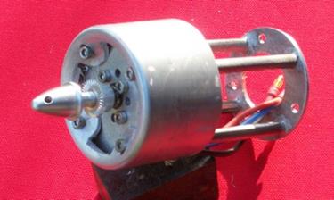 Update April 2015… David has constructed an
all welded aluminium extension motor mount. Attached
(right) is a picture of the Puppeteer motor mount with the nose cover (from a Febreeze aluminum aerosol can!). The cover hides and
secures lead sheet which is wrapped around the
Update April 2015… David has constructed an
all welded aluminium extension motor mount. Attached
(right) is a picture of the Puppeteer motor mount with the nose cover (from a Febreeze aluminum aerosol can!). The cover hides and
secures lead sheet which is wrapped around the 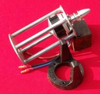 mount to get the balance point right. It is now painted drab olive to
match the fuselage and nose ring. ‘I realised
that I didn’t know where the balance point should be but found it on the ’net.
. Looks as if I shall need to add a bit more lead than the 100 grams already
fitted. I will send a photo of the aircraft soon’. With the slight side and
down thrust built in, and also those allen screws, it
all looks a very well engineered unit.
mount to get the balance point right. It is now painted drab olive to
match the fuselage and nose ring. ‘I realised
that I didn’t know where the balance point should be but found it on the ’net.
. Looks as if I shall need to add a bit more lead than the 100 grams already
fitted. I will send a photo of the aircraft soon’. With the slight side and
down thrust built in, and also those allen screws, it
all looks a very well engineered unit.
Interesting when you look at the picture
to the left…How did that motor get into that All Welded extension mount ?
Mmmm….
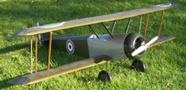
The finished electrified version of the Puppeteer is shown in this picture and has just had its maiden flight. ‘A BIT TWITCHY’ was the finding of David C and for the next session more lead is going to be added inside the front cowling to move the CG forward. This should help with stability and handling.
More flights to come !
OK ! another change of subject now…..
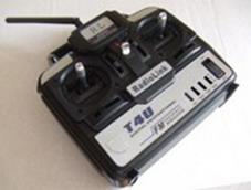
A newcomers guide of the 2.4 Gig ‘Spread Spectrum’ radio control
These notes about ‘Spread Spectrum Technology’, ‘Frequency Hopping’ and the use of the ‘2.4 Gig band’ for model radio control are intended for newcomers. They introduce the most exciting innovation for radio control models in the last decade.
Frequency bands allotted for model control are usually wide enough to fit in around thirty crystal controlled channels. Each channel with its plug-in crystals can control a model without radio interference to any of the other 29 frequency channels. This method has been used from the mid sixties and has, and still is, a superb well developed and proven system for model control. HOWEVER accidental switching on of a transmitter on the same frequency at your flying site can be catastrophic for the model in the air at that time.
 Radio
Control equipment using the 2.4 Gig (gigahertz) band however, ‘share’ this
radio band in a very different way. They use all the frequency channels in a
quick random type scatter, This method ‘spreads’ the transmission of each
system over the whole of the 2.4 Gigahertz radio band. ANYBODY CAN SWITCH THEIR
TRANSMITTER ON AT ANY TIME WITHOUT INTERFERING WITH ANY OTHER USERS MODEL.
Radio
Control equipment using the 2.4 Gig (gigahertz) band however, ‘share’ this
radio band in a very different way. They use all the frequency channels in a
quick random type scatter, This method ‘spreads’ the transmission of each
system over the whole of the 2.4 Gigahertz radio band. ANYBODY CAN SWITCH THEIR
TRANSMITTER ON AT ANY TIME WITHOUT INTERFERING WITH ANY OTHER USERS MODEL.
Each transmitter spends so little of its time on any single frequency channel, that virtually zero interference is produced to any of the other model control systems.
As a result of this continual ‘frequency hopping’ of the whole (or part) of 2.4 Gig radio band, many R/C systems can be used alongside each other without interference. All the systems simply ‘SHARE’ the same 2.4 Gig radio band.
The 2.4 Gig radio band is the largest radio band that R/C modellers can use (it has the equivalent of up to 80 channels!) but there are other commercial users of the band. In practice (based on recent years) 2.4 Gig model radio control has proven to be interference free from other users, Partly, perhaps because other commercial users are outside the range of your club flying site.
2.4 Gig transmitters use a rapid random like ‘frequency hopping’ transmission but each transmitter is produced to have its own random like sequence of its ‘frequency hopping’ called a ‘code’. With 80 channels to hop around in, the chances of two transmitters with an identical frequency hopping sequence, is one in several billion! To find those two identical transmitters down at your local club site is about the same as being run over by a bus several times and living to tell the tale!
Manufactured frequency hopping
receivers have no idea what transmitter they are going to end up with! And they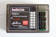 have no frequency spot sequence built into them! As a result, they just sit and
freeze their servos with any transmitter that tries to control them.
Fortunately, they have a tiny memory chip built into the front end which is
empty. The receiver will remember the random sequence ‘code’ of any transmitter
within a second of pressing the tiny button on the side of the receiver. This
is called ‘binding’ the receiver to a particular transmitter. Because all other
transmitters have a different frequency sequence (‘code’), the receiver will
refuse to work with them unless the ‘binding’ process is done again with a
different transmitter.
have no frequency spot sequence built into them! As a result, they just sit and
freeze their servos with any transmitter that tries to control them.
Fortunately, they have a tiny memory chip built into the front end which is
empty. The receiver will remember the random sequence ‘code’ of any transmitter
within a second of pressing the tiny button on the side of the receiver. This
is called ‘binding’ the receiver to a particular transmitter. Because all other
transmitters have a different frequency sequence (‘code’), the receiver will
refuse to work with them unless the ‘binding’ process is done again with a
different transmitter.
The number of Frequency Hopping (Spread Spectrum) systems that can work together is quoted by different manufacturers from 20 systems to ‘over 200 systems’ (Graupner HoTT system). Both of these figures are in excess of a ‘safe’ number of model aircraft in the sky simultaneously down at your local club. Perhaps the lower figure of 20 could equal a model boat club activity on a very exciting Summer, day!
2.4 gigahertz receivers have a very short aerial, just 3 centimetres at the end of a short 5/7cm coax flex. The effective 3cm bit is best outside the model if possible. In a boat, the 3cm end bit must be above the water level. 2.4 Gig is virtually ‘line of site’ contact between your Transmitter and the Reciever aerial. Thought has to be given to metal type objects that get in the way of this, i.e. batteries, motors, helicopter metal parts and carbon fibre. Longer coax replacement aerial flexes are available but intended for replacement of transmitter aerials. If applied to receivers the longer coax covering unfortunately produces less range owing to coax signal loss. Model boat application probably OK but aircraft, some serious thought needed.
The signal intensity from the short (around 12 cm) transmitter aerial forms a doughnut shape around the aerial axis. The least signal strength (range) is pointing the aerial at the model. The 45 degree (click) angle would seem to be the most practical optimum for aircraft water and land models.
Spread spectrum (frequency hopping) systems ‘share’ the 2.4Gig radio band. This results in a small loss of range as the number of users at the model site increases. A particularly active hobby exhibition venue where 2.4 Gig systems are used extensively for aircraft, boats and land models simultaneously, may well find some range reduction. Particularly with aircraft which use the greatest range.
So what are just the practical advantages of using ‘Spread Spectrum’ ‘Frequency Hopping’ ‘2.4 Gig Radio’ for model control?
No more expensive box of plug-in crystals to change frequency! (around £10 a pair, 15$ US)
No more long cumbersome transmitter aerial to bend/break or poke someone’s eye out!
No need to check who is on what frequency!
No need to display a frequency flag!
No need to get a frequency peg from transmitter control!
No need to worry about testing the model controls and motor, just switch on and test!
No need to worry about ‘metal to metal’ or electric motor interference, 2.4 Gig is immune!
20 or more models can be controlled at one venue!
A 2.4 Gig transmitter and receiver ‘Combo’ can cost as little as £26.00!, Just use all your existing batteries and servos. See Page7.
The 2.4 GHz SS band has been now accepted for the future of Radio Control Models (2015)
Some interesting facts about our existing Radio Control Frequencies………
The 27 MHz band still available for R/C use including…
Marine and Citizens Band Radio. Speech.
Model aircraft control.
Model control boats and surface vehicles.
Toys model control.
Industrial.. very little, phased out.
The 35/36/40*/72 MHz band…These are protected frequencies for Radio Control Models.
Model aircraft only. No other users legally allowed.
*New Zealand only. EU 40MHz is for surface models.
The 2.4 Gigahertz Model Radio Control band…is however shared with many other people…
Wireless mouse keyboards.
Cordless telephones.
Baby monitors (audio).
Baby monitors (Video).
Bluetooth (short range personal area networks).
Cordless headphones.
Car alarm hand sets.
Microwave ovens (domestic).
Television video senders.
Garage door wireless type.
Radio control toys.
RF activated sulphur street lighting (phasing out).
ISM (industrial scientific medical) research projects.
WISP wireless internet service providers.
Wireless Video for security cameras.
ZigBee wireless data networks.
High speed point to point links that use propriety protocols.
Industrial Microwave:-
Fruit driers.
Plastics pre heaters.
Moisture removers.
Building to Building video and speech up to 50 miles.
Radio Ham usage up to 1500Watts for carrier wave and single sideband Greater than 50 miles range.
Over Counter 2.4 Gigahertz transmitters 50 miles capable.
Police Robot surveillance vehicles. Video feedback. (bomb squad).
Military video flying surveillance drones. (30 miles+).
Flying spy cameras, domestic, video transmission. Police use.
Model aircraft (all types).
Model boats (all types) (except under water)
Model land vehicles, cars, tanks etc.
Commercial applications are being added to this list as you read this text. We simply share this band with whoever decides to use it. There is little or no control.
Model aircraft radio control systems use ‘Spread Spectrum’ techniques on the 2.4 Gigahertz band. The transmitter ‘scatters’ its transmission
over many of the frequency channels in a random like fashion. This allows a maximum of signal to get to the receiver.
This method allows other users (fixed frequency and Spread Spectrum types) to use the band too.
Most commercial transmissions are confined to Towns and Cities and are short range devices but when considered all together,
can produce asignificant amount of background interference.
Industrial, Ham Radio and video systems with up to 50 miles range are also in the cook-pot of possible future problems for the use of the 2.4 Gigahertz band for radio control models.
A ‘good’ flying site would be several miles away from Towns and Cities. Also several miles from Industrial complexes.
If you can see the stars at night from your flying site…..then you got a good site for 2.4 Gig R/C.
If you have got this far reading about the 2.4 Gig phenomena then (pat yourself on the back!) I must now pass you on to a Radio control Guru that I met on the web. This guy has lived the journey of 2.4 Gig Model Radio Control and has the background to predict the possible future of this system…….
Spread-Spectrum
RC Systems, How they started and how we got there. By Barry Lennox NZ.
Please
note that the Barry Lennox topic has been shifted to Page 42
![]()