Page 14
![]()
![]()
![]()
Some useful links……![]() BECdistriburion
BECdistriburion ![]() ElectroJumble
ElectroJumble
TUNED CIRCUITS USED IN MODEL RADIO CONTROL SYSTEMS.
The following notes dwell on the coil and capacitor tuned circuits that have been used in model radio control transmitters and receivers for the last seventy years or so. Many of these tuned circuits are buried in the complete schematics of both Transmitters and Receivers and are often overlooked as a ‘component’ in themselves. Often, these tuned circuits can be looked upon as a ‘three terminal device’ with some versatility as to which is the input or output or ground terminal!
These initial notes use the front end tuned circuit of a typical R/C receiver. This is done simply to exclude any surrounding transistor circuitry which would complicate the use of these ‘three terminal devices’. In practice, particularly in transmitter circuitry, these tuned circuits are used not only to suppress unwanted frequencies but also perform better coupling from one part of the circuit to the next.
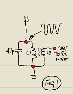
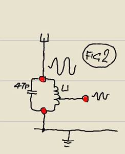 Fig 1 shows the aerial
input tuned circuit of a typical radio control receiver. L1 and the 47p
capacitor get excited by the received transmitter signal and begin to oscillate.
L2 which is a few turns of insulated wire around L1, pulls in a small amount of
this exciting activity to produce an input to the receiver. The low number of
turns of L2 does not load the tuned circuit significantly, so both selectivity
and sensitivity are not unduly effected. L2 is not tuned and because of the low
number of turns, gives a much reduced signal voltage. However, the current
capability is higher and more capable of driving the input transistors of the
receiver circuitry.
Fig 1 shows the aerial
input tuned circuit of a typical radio control receiver. L1 and the 47p
capacitor get excited by the received transmitter signal and begin to oscillate.
L2 which is a few turns of insulated wire around L1, pulls in a small amount of
this exciting activity to produce an input to the receiver. The low number of
turns of L2 does not load the tuned circuit significantly, so both selectivity
and sensitivity are not unduly effected. L2 is not tuned and because of the low
number of turns, gives a much reduced signal voltage. However, the current
capability is higher and more capable of driving the input transistors of the
receiver circuitry.
For these notes only! (♫Da♫Didi♫Da♪) :- L1 is a tuneable ferrite slug 4.5 mm coil former. 27 MHz 10.5 turns 0.4mm ECW…. 35 MHz 7.5 turns 0.4mm ECW….. 40 MHz 6.5 turns 0.4 ECW….. L2 is 2 or 3 turns of 0.4 ECW close wound around L1.
Another variation of this tuned circuit is shown in Fig2. this uses a tap of L1 approximately one third up from the negative ground end of the coil. Although this method works well, practically it lacks easy adjustment of the tap to produce optimum results.
Yet a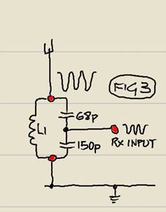 further variation of this
tuned circuit is shown in Fig 3. this time the
tuning capacitor is split into two capacitors in series offering a combined
capacitance of 47p (near enough!) across the coil L1. this
method works quite well and allows fairly simple adjustment of the output
coupling point (by selection of the capacitor values) to suit the input
further variation of this
tuned circuit is shown in Fig 3. this time the
tuning capacitor is split into two capacitors in series offering a combined
capacitance of 47p (near enough!) across the coil L1. this
method works quite well and allows fairly simple adjustment of the output
coupling point (by selection of the capacitor values) to suit the input 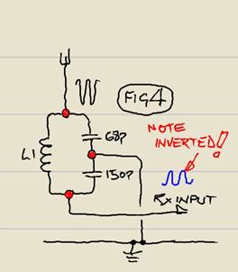 resistance of the receiver
circuit. (for interest only the MC3361B NBFM receiver
chip input is around 3K)
resistance of the receiver
circuit. (for interest only the MC3361B NBFM receiver
chip input is around 3K)
Fig 3 is an interesting application as swapping the terminals around a bit, it can become a ‘Pi-network filter’!! These filters are used extensively in the output stages of most Radio Control transmitters, they not only give effective suppression of unwanted ‘out of band’ RF radiation but also allow adjustment of the coupling to the aerial for maximum output.
Fig 4 shows how the terminals could be re-located to produce a Pi-network filter. OK…OK..it don’t look like a Pi-filter! But some ‘re-drawing only’ of the schematic is done in Fig 5 and Fig 6 to show a more text book version. DAVID CAUDREY’s Page 9 shows many R/C transmitter circuits. Without exception, all versions use Pi-network filters in the output stages. Often the PA output transistor is biased OFF (Class C) and only pulses ON at the RF frequency. This is far from sinusoidal but the ‘flywheel’ effect of the (usually) two Pi-network circuits gives a close approximation of good sine wave RF output. The use of two Pi-Filter stages coupling the aerial usually suppress all harmonic content (and sub-harmonic, the half frequency Xtal ! ) by around 40db.
The values of the capacitors particularly in the second filter can
be selected to change the final output impedance to suit the type o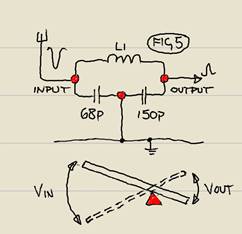 f aerial used. Often these
final adjustments are done empirically in the workshop with the relevant test
equipment. As R/C transmitter aerials are telescopic, some consideration has to
be given during this process of the current drain of the PA transistor under
differing aerial lengths, also current drain with no aerial fitted. The final
selected component values must prevent a thermal runaway of the PA transistor
under all possible conditions that the modeller would do with the aerial.
f aerial used. Often these
final adjustments are done empirically in the workshop with the relevant test
equipment. As R/C transmitter aerials are telescopic, some consideration has to
be given during this process of the current drain of the PA transistor under
differing aerial lengths, also current drain with no aerial fitted. The final
selected component values must prevent a thermal runaway of the PA transistor
under all possible conditions that the modeller would do with the aerial.
While rambling about Pi-Filters and Class C Tx output transistors and ‘Flywheel Effect’ it is worth mentioning that the conversion of the output transistor ‘pulses’ to a near perfect sinusoidal RF output can rely on the ‘mechanical quality’ of the coils used in the output Pi-Filter network. Larger air spaced wound coils using around 1mm diameter copper will give a better ‘flywheel’ effect. The problem is that some form of capacitive tuning has to be introduced.
Fig 5 is simply Fig 4 re-drawn 90 degrees clockwise. Note that the output is a bit like a lever with the fulcrum to one end. I.E. a light input can produce a powerful output. Also note that the circuit is symmetrical and therefore can be used in a reverse direction which INCREASES the output voltage swing. The output voltage swing of the Pi-network circuit straddles the negative earth supply i.e. half of the voltage swing is below battery negative! Some care is needed if using the circuit to couple a pre-amp to the base of a PA output transistor. RF transistors often have a low reverse base/emitter breakdown voltage of around three volts. Care must be taken not to exceed this voltage as the poor output transistor could die! (sad).
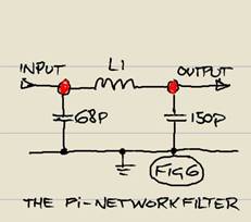
AT LAST!>>>>WE HAVE GOT TO THE Pi-NETWORK FILTER CIRCUIT THAT YOU SEE IN RADIO TEXT BOOKS AND THIS IS SHOWN IN FIG 6 AGAIN only a re-draw of Fig5. Absolutely nothing electronically has changed since we introduced the circuit in Fig 4. Obviously this Pi-network schematic is now shown in its simplest schematic form as you see in electronic books. I can’t help thinking that not only its operation is not easily comprehended looking at this schematic but also its many capabilities are lost in the simplicity of this well accepted diagram.
 THIS LAST LITTLE PICTURE
IS FOR FUN ! It shows the operation of
a Pi-Network Filter Massively slowed down ! The
oscillation you see would normally be around 35 million times each second (Radio
Control). All you would see would be a blur
! Note also that the electronic oscillations would be much less Clunky
than the simple picture suggests ! (i.e. We wouldn’t want the printed circuit board to jump out
of the back of the transmitter !)
THIS LAST LITTLE PICTURE
IS FOR FUN ! It shows the operation of
a Pi-Network Filter Massively slowed down ! The
oscillation you see would normally be around 35 million times each second (Radio
Control). All you would see would be a blur
! Note also that the electronic oscillations would be much less Clunky
than the simple picture suggests ! (i.e. We wouldn’t want the printed circuit board to jump out
of the back of the transmitter !)
It may be of interest that in this example the voltage swing at the input is exactly the same as the voltage swing at the output. Even this simple version can offer up to 20db suppression of harmonics and spurious RF content being transmitted.
DAVID CAUDREY STARTED THIS DISCUSSION ABOUT Pi-NETWORK FILTERS BY EMAILING HIS ANALITICAL CONTENT BELOW.
THANKS FOR READING !